About Meshing Techniques

There are different meshing techniques you can assign to one or several domains or 3D volumes.

You can create specifications to remesh local areas using a different technique or mesh size from the original mesh defined in the global parameters of the surface mesh.

You can also redefine node positions for free edges within the remesh area to better suit nearby element sizes.

This page discusses:

2D Meshing Techniques

You can create specific meshes on domains using the following mesh types:

  • Frontal Quadrangles
  • Frontal Triangles
  • Mapped Mesh
  • Mapped Free Mesh
  • Minimal Mesh
  • Bead Mesh
  • Half Bead Mesh

The following image shows the results of remeshing a domain with the frontal quadrangle method:

By contrast, you can remesh the same domain with the frontal triangle mesh method:

Mapped Meshes and Mapped Free Meshes

The mapped mesh method generates a mesh using quadrangle elements only, whereas the mapped free mesh generates a mesh using both quadrangle and triangle elements:
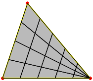
However, you can use the Split quadrangles option to convert the quadrangles into triangles at any time.

For the mapped mesh and mapped free mesh methods, you can have rectangular, cylindrical, or ring topologies. For the rectangular topologies, you can enhance the mesh quality by repositioning the vertices that define the perimeter of the domain.

For domains with a rectangular or triangular topology, symbols appear on the selected domain to represent the corners of the domain (C0, C1, C2, and C3 for rectangular domains; C0, C1, C2 for triangular domains). In the following figure of a mapped mesh domain, the C0, C1, C2, and C3 symbols display to represent the four corners of the domain. This is true even if the selected domain has more than four corners.
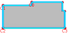
You can change the corner positions to enhance the mesh quality. To change the position of a corner, select the corner you want to change, and select another vertex.
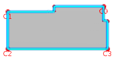
For domains with a cylinder or ring topology, corners are imposed and not displayed; you cannot modify them.

Bead and Half Bead Meshes

Similar to mapped meshes and mapped Free meshes, you can reposition vertices for a bead mesh and half bead mesh. To select the domains for a bead mesh, you must select two vertices; to select the domain for a half bead mesh, you must select three vertices.
3D Meshing Techniques

You can create specific meshes on 3D volumes using the following mesh types:

  • Sweep Technique (fill with hexahedral mesh or hex-dominant mesh)
  • Structured Technique (fill with hexahedral mesh only)
  • Free Technique (fill with tetrahedral mesh or tet-dominant mesh)

Sweep Techniques

You can assign a sweep technique to a specified volume. You can select multiple 2D domains as the source and a single 2D domain as the target. The app colors the source domains blue and colors the target domain magenta. When you are creating the mesh, the app colors the sweep mesh volumes yellow.

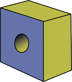
The following figure shows a volume consisting of a block with a central hole:

The app creates the mesh on the source side and then copies the nodes of that mesh along an edge known as the sweep path, one element layer at a time, until the target side is reached. The following figure shows the extruded swept mesh:

Structured Techniques

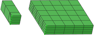
Consider two volumes, a narrow block and a thick plate:

To create four layers, you might assign four elements along a short edge (indicated in green above). The app chooses the narrow direction as the preferred sweep direction, which results in a random choice for the narrow block on the left and results in a unique choice for the thick plate on the right. As a result, sweep techniques can produce undesirable transitions through the material thickness, as shown in the narrow block on the left:

You can use a structured technique to overcome the limitations of the sweep technique:


The app colors structured volumes dark green (to distinguish them from the light green color of good quality elements).

A structured technique fills a rectangular volume with a fully regular hex mesh. Structured meshing offers the following advantages:

  • Avoids undesirable transitions in sweep volumes.
  • Produces higher-quality meshes.
  • Produces meshes faster.
  • Reduces the amount of partitioning to give compatible meshes.

The structured technique is capable of generating usable elements for highly distorted volumes. When a rectangular volume is relatively well-shaped, structured meshing is used by default. For distorted volumes, depending on the particular shape and angles, the app automatically determines the optimal meshing technique. However, you can manually change the meshing technique for each volume using the local mesh specification.

Depending on the various angles of the volume, the default mesh technique for a distorted rectangular volume can be a sweep technique. If the quality is insufficient, you can assign a structured technique. Structured techniques produce fast, high-quality meshes, and they minimize the mesh transitions that you commonly find on the source and target sides of sweep volumes. The app colors the volumes dark green.

Free Techniques

If you are not satisfied with the mesh quality from a sweep or structured technique, you can reapply a free technique to one or more volumes. The free technique is a local mesh specification that fills a specified volume with either a combination of tetrahedral and pyramidal elements or all tetrahedral elements.