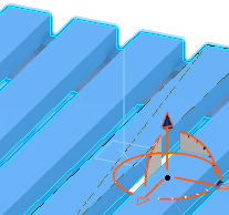
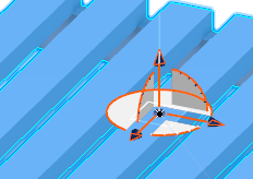
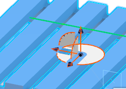
- Click Mechanical Port
 and select the resource on which you want to create the port.
 The
Create Mechanical Port dialog box appears, asking:
Would you like to create an Axis System?
- Click Yes.
A context toolbar appears, as well as a plane selector, and the
Robot.

- Create an axis system by using Define Plane by Selecting Point / Axis / Circle Center
 (selected by default) and the plane selector.
- Move the selector so that you have selected the desired plane.
- Click on the plane.
The
Robot snaps to the selector.

- Click Define New Orientation of X-Axis
 , and move the mouse over the content until you see a green line that shows the direction you want for the X-axis.
The
Robot shifts to show the next direction for the X-axis.

- Click Finish
 .
.You have created an axis system.
The Mechanical Port dialog box appears.
- Select Connector Port, and click OK.
The connector port is created.
You can choose to create other types of mechanical ports from the Mechanical Port dialog box. If you have other axis systems created, you can select one of them for a mechanical port from the Mechanical Port dialog box.