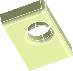
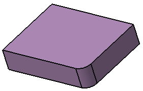
Create an Edge Fillet
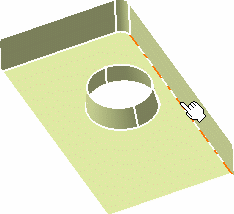
You can define fillet by selecting edges.
- From the section of the action bar, click .
-
In the
Object(s) to fillet
box, select the edge to be filleted.
You can also select a face, provided there is no ambiguity in the edge(s) to be filleted.

-
In the Extremities list, select the desired type of
extremity for the fillet.
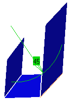
- Straight: no tangency constraint is imposed at the connecting point between the fillet and the initial support, generating sometimes a sharp angle.
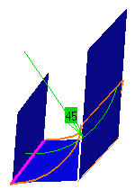
- Smooth: a tangency constraint is imposed at the connection between the fillet surface and the support surfaces, thus smoothing the connection.
- Maximum: the fillet surface is limited by the longest selected edge.
- Minimum: the fillet surface is limited by the shortest selected edge.
(Refer to Creating Shape Fillets)
-
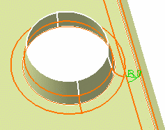
In the Radius box, enter the value of the fillet.
A preview of the fillet appears.
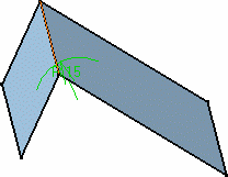
-
In the Propagation list, select the desired
propagation:
- Tangency: the fillet is propagated up to the
first edge that is not continuous in tangency.
The tangent continuous edges of the selected edge are managed to ensure a better fillet stability and robustness (More fillets are automatically rerouted in case of design changes).
- Minimal : the fillet is propagated up to the first geometric limitation.
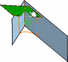
- Intersection: the fillet is propagated to all the edges that have been generated by intersecting the features.
- Tangency: the fillet is propagated up to the
first edge that is not continuous in tangency.
-
Select the Conic
parameter check box.
This check box allows you to vary the section of the fillet.
Important: For a parameter comprised between or equal to: - 0.5, the resulting curve is a parabola.
- 0 < parameter < 0.5, the resulting curve is an arc of an ellipse
- 0.5 < parameter < 1, the resulting curve is a hyperbola.
Important: - Conical fillets may produce internal sharp edges. However, healing is used to smooth these sharp edges. Refer to for more information.
- Optional: Select the Trim support check box to relimit the support elements and assemble them to the fillet.
-
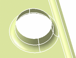
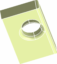
Click OK to create the fillet surface.
The surface (identified as EdgeFillet.xxx ) is added to the tree.

Important: - The selection of the feature prevails over the selection of the sub-element. To select a sub-element, you need to apply the Geometrical Element filter in the User Selection Filter from the App Options panel. For further information, see 3DEXPERIENCE Native Apps: Native Apps Advanced: Selecting: Selecting Using a Filter.
- While editing the edge fillets created by selecting Tangent intersection edges in Intersection mode, a warning message appears. It states that only edges resulting from intersecting features can be selected in the intersection mode.
- You can apply the edge intersection filter (which affects all the features in a model) in the User Selection Filter toolbar.
- The behavior of Propagation box (which
deals with sub-elements) in the Edge Fillet
Definition dialog box is dependent on the edge
selection filter in the following ways:
- If Tangent Intersection Edges (i. e. C1 mode) is selected, the Propagation box remains unavailable and displays Tangency.
- If Intersection Edges (i.e. C0 mode) is selected, the Propagation box remains unavailable and displays Intersection.
- If no mode is selected, a standard feature edge is created with the propagation of your choice. In this case, you can select either Tangency or Minimal in the Propagation list.
- When you edit an existing edge fillet, the edge intersection filter automatically changes to a mode (C1 or C0), which was active at the time of edge fillet creation. If you change the mode during edition, existing data is discarded. The edge fillet cannot contain heterogeneous features.
- If you want to replace an existing edge, the new edge should be of the same propagation type. That is, if the edge is a C0 edge, the replace edge should also be a C0 edge. Similarly, for C1 edge, replace edge should be a C1 edge.
