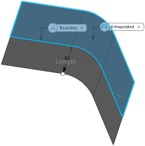
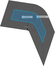
Extrapolating Surfaces | |||||
|
| ||||
-
From the Create section of the
action bar, click
Extrapolate
 .
.
-
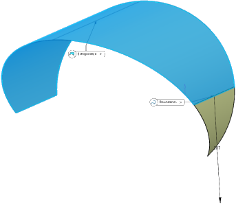
Pause over a boundary in the work area.
The command automatically computes the geometrically feasible surface(s) that can be extrapolated. There are two possible scenarios:
- When only one surface is found,
 appears over the selected boundary, along with a tooltip. The tooltip
contains information about the boundary and the surface, as follows:
Edge/Surface/Geometrical Set.1
SUPPORT:
Surface.1/Geometrical Set.1/Extrapolation Surface_Representation15498 --- IN_WORK
Click the surface boundary.
- When the command finds more than one surface,
 appears. The accompanying tooltip indicates the boundary and its
possible supports, one of which can be used as the surface to be
extrapolated, as
follows:
appears. The accompanying tooltip indicates the boundary and its
possible supports, one of which can be used as the surface to be
extrapolated, as
follows:Edge/Surface/Geometrical Set.1 POSSIBLE SUPPORT: Extrapolate.1/Geometrical Set.2/Extrapolation Surface_Representation15498 --- IN_WORK Surface.2/Geometrical Set.2/Extrapolation Surface_Representation15498 --- IN_WORK
In this case, you can perform either of the following:
- Right-click to display a list of all the possible surface solutions. Pause over one of the entries to display the corresponding surface in the work area. Click to confirm your selection.
- Click the surface boundary. The command automatically selects the first entry from the list of possible surface solutions and computes the surface.
- When only one surface is found,
- Optional:
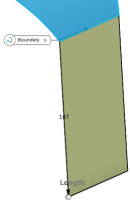
In the Extrapolated box, select the surface to be
extrapolated.
Note: This step is only necessary if the command is unable to automatically compute the surface or if you want to manually select it.The surface selection appears in the Extrapolated box.
-
In the Type list, select the extrapolation type.
Option Description Length Enter the value in the Length box or use the handles in the work area. Note: It is recommended to enter a positive value.Up to element The Up to box is enabled. Select a plane or a surface that intersects the extrapolated surface to relimit the extrapolation. - In the Continuity list, select Tangent.
- In the Continuity list, select Curvature.
- Optional:
To activate the approximate boundaries modem clear the Exact
boundaries check box.
This mode allows a more tolerant approach of the skin border reconstruction.
- Optional:
Select the Deviation check box and specify a desired value in the box.
In some cases, the extrapolation operation fails, due to creation of a gap between adjacent surfaces. The deviation value avoids creation of such gaps by considering a little difference between the obtained and theoretically calculated extrapolated surface result. This makes the extrapolation operation more robust. In case of a failure, an error message informs you about the required changes in the deviation value.
Notes:- This check box is only available in curvature mode.
- By default, when the Deviation check box is selected, the default deviation value is the point tolerance.
- Optional:
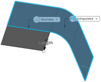
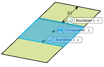
In the Boundary box, select several boundaries.
All surface sides are extrapolated applying the same type (Length or Up to element) and value (the length or the up-to element).
-
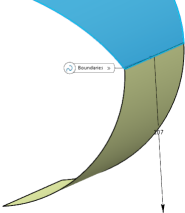
In the Extremities list, select the extremities conditions between the extrapolated surface and the support surface.
- Tangent: The extrapolation sides are tangent to the edges adjacent to the surface boundary.
- Normal: The extrapolation sides are normal to the original surface boundary.
-
In the Propagation list, select the propagation mode.
Option Description Tangency continuity Propagates the extrapolation to the boundary's adjacent edges. Point continuity Propagates the extrapolation around all the boundary's vertices. - Click OK.

