Creating Extruded Surfaces | |||
| |||
-
From the Create section of the action bar,
click Extrude
 .
.
-
From the SurfaceCreate
section of the action bar, click
Extrude
.
-
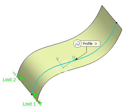
In the First Limit and Second Limit boxes, define the extrusion limits.
- Length: enter length values or use the graphic handles to
define the start and end limits of the extrusion. Here we defined a length of
30mm for First Limit and
80mm for Second Limit.
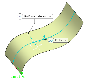
- Up-to-element: select a geometric element. It can be a point,
a plane or a surface (wires are not allowed). If a point is specified, the up-to
element is the plane normal to the extrusion direction passing through the given
point.
Here we selected a point as First Limit and a plane as Second Limit.

You can also select different extrusion limits, for instance a length for First Limit and an Up-to element for Second Limit:
Important: - The Up-to element can intersect the profile and the surface to be extruded. In the latter case, it must completely cut the surface and there should not be any partial intersections of the up-to element with the surface.
- If you select two up-to elements, they must not cut each other within the surface to be extruded.
- Length: enter length values or use the graphic handles to
define the start and end limits of the extrusion. Here we defined a length of
30mm for First Limit and
80mm for Second Limit.
-
Click Reverse Direction
 or the red arrow in the 3D geometry to display the extrusion on the other side of the selected profile.