Creating and Manipulating Geometry | |||||||
|
| ||||||
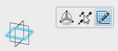
- Select a plane in the 3D area.
-
Click
Sketcher
 in the
context toolbar.

The Sketcher app is activated. -
Create a profile and exit
Sketcher.

-
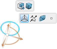
Select an element of the sketch and click
Robot
 in the
context toolbar.
The Robot is connected to the sketch and another context toolbar appears.
-
In the
context toolbar, select:
-
Create features mode
 ,
,
-
Global Mode
 ,
,
-
Same dimension

-
Create features mode
-
Drag the
Robot handle.
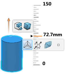
The sketch is translated and Translate.x is added to the tree.
The Robot is replaced by an arrow manipulator and a ruler appears. You can use the both the manipulator and the ruler for further manipulations.

Tip: Clicking the value at the ruler opens an edit field where you can change the numerical value for the translation operation. -
Press
Esc
to undo the last step.
The Robot is reset and the feature is removed from the tree. The Robot context toolbar remains active.
-
Click
Upper dimension
 and manipulate the sketch again.

An extruded feature is created and the Pad.x node is added to the tree.Note: Ctrl + dragging the Robot handle creates a pad with mirrored extent. - Press Esc to undo the last step.
-
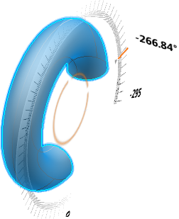
Drag the
Robot
on a reference element. Rotate the
Robot
handle in the required direction and specify the angle.
You can use the following as a reference element:
- Line or linear edge
- Axis of the Robot

A shaft is created about the reference element and the Shaft.x node is added to the tree.
-
Draw a profile on the surface of a pad feature. Click the profile and drag the handle of the
Robot
as shown:

A Pocket is created and the Pocket.x node is added to the tree.Note: Ctrl + dragging the Robot handle creates a pocket with mirrored extent. -
Drag the
Robot
on a reference element. Rotate the
Robot
handle in the required direction and specify the angle.
You can use the following as a reference element:
- Line or linear edge
- Axis of the Robot

A groove is created about the reference element and the Groove.x node is added to the tree.
- Press Esc to undo the last step. Keep only the sketch removing the extrude feature.
-
From the
Model
section of the
action bar, click Plane
 to create a plane selecting xy plane as
Reference
and an
Offset.
-
Select an element of the sketch and click
Robot
 in the
context toolbar.
-
Drag the handle toward the plane until the copilot
appears.
For more information, see Copilot.
A pad up to the plane is created. -
Press
Enter
or click the background to validate the command.
The Robot is disconnected.