Using Global and Local modes | |||||
|
| ||||
-
Select a face of the extruded feature and click
Robot
 in the
context toolbar.
Global mode
 and
Local mode
 are now available.
-
Click
Local mode
 ,
and
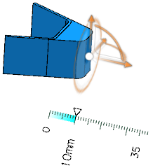
Translate
 and manipulate the feature.
- Press Esc to undo the last manipulation.
-
Click
Upper dimension
 and manipulate again the feature.
The topology of the feature is created using the Volume Extrude command and Volume Extrude.x is added to the tree.
- Press again Esc to undo the last manipulation.
-
Click
Local mode
 and manipulate again the feature.
The feature is modified locally depending on the selected sub-element. A Transform.x feature is added to the tree.
-
Double click the feature or the modified face in
work area.
The Modify Face Definition dialog box opens and the original face is highlighted.
You can edit the following parameters:
- Recognition context
-
You can modify faces from the
context toolbar
in
Local mode
 while ignoring constant fillets and chamfers.
-
- Modification within the Recognition context range
-
If a face is connected to another face by a constant fillet (resp. chamfer) whose radius (resp. length) is within the specified recognition context range, both the selected face and the connecting fillet (resp. chamfer) are moved together when you modify the face in
Local mode
 .
.
-
Everything happens as if three steps had been manually performed in the following order:
- The fillet (resp. chamfer) is unset.
- The clicked face is moved.
- The fillet (resp. chamfer) is set back.
- As a result, the matter has been added at the connected face's side, and not at the clicked face's side.
- Modification outside Recognition context range
-
If the radius or length, respectively, is outside the specified recognition context range, only the selected face is moved. As a result, the matter is added at the selected face's side.
For more information on the ranges for the different industries see About Recognition Context Ranges
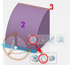
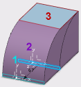
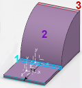
- Below is an example illustrating the fillets radii range influence of Recognition context setting. The initial feature consists of two orthogonal faces (1 and 3) connected by a constant fillet (2). Face 1 is selected face for modification.
- Mode
-
You can change the transformation mode.
Click
Global mode
 ,
Same dimension
 .
.
- Transform Faces
-
- Faces
- You can select additional faces to be transformed.
- Transform Type
-
-
Translate: You can define the translation
Direction
and
Length.
You first have to define the direction. Then you can change the length either by editing the text box or dragging the handle in the work area.

-
You can select the following elements as a reference to specify the translation direction:
- Line or linear edge
- Plane or planar face
- Axis of the Robot
-
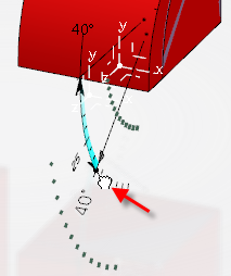
Rotate: You can define the rotation
Axis
and
Angle.
You first have to define the rotation axis. Then you can change the rotation angle either by editing the text box or dragging the handle in the work area.
-
You can select the following elements as a reference for rotation:
- Line or linear edge
- Axis of the Robot
-
Translate: You can define the translation
Direction
and
Length.
- Offset Faces
-
- Faces
- You can select additional faces to be offset.
- Offset
- You can change the offset distance either by editing the text box or dragging the handle in work area.
