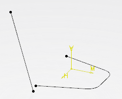
- Sketch a required profile.
- Use Sketcher to create a line in another plane than that of the profile, created in the previous step.
The line direction should different from the plane normal direction of the first sketch.
- Select first the sketch and then the line using Ctrl.
- Select Robot
 and Upper dimension and Upper dimension  . .
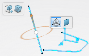
- To manipulate the geometry, drag the Robot translator.
The extruded surface is created in direction of the line. 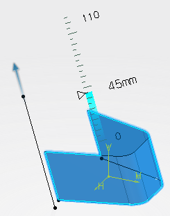 - Press Esc to undo the last manipulation.
- Select both end points of the sketch using Ctrl and click Create Line
 in the context toolbar. in the context toolbar. A line is created between the corner points. 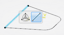 - Select first the sketch and then the line using Ctrl.
- Select Robot and Upper dimension .
- Rotate the Robot wheel.
A revolution surface is created using the line as revolution axis.  - Click in the background to validate the command, exit the context toolbar, and to disconnect the Robot at the same time.
|
