About Chordal Fillets | ||||
|
| |||
Edit Fillet Values
The Control points box lists all the points of the part used to form the chordal fillets and the chordal length applied at these points. If you select any of these values, the corresponding constraint is highlighted in the work area (and vice-versa).
| Tip: To sort the list by name and value, click on Point on Edge and Parameters tab respectively. |
Propagation
Two propagation modes are available:
- Minimal: edges tangent to selected edges can be taken into account to some extent. The app continues filleting beyond the selected edge whenever it cannot do otherwise.
- Tangency: tangencies are taken into account so as to fillet entire edges. The tangent continuous edges of the selected edge are managed to ensure a better fillet stability and robustness (more fillets are automatically rerouted in case of design changes).
Limiting Elements
- You can define one or more limiting elements.
- You can create the limiting elements using
context menus
available from the
Limiting element(s) box.
If you create any of these elements, the corresponding icon is displayed in front of the Limiting element(s) box. You can click this icon to edit the element.
- You can create limiting elements by clicking on the edge to be filleted. This element is displayed as a blue disk.
- You can select points as limiting elements. These points must be located on the edge to be filleted and they must be created using the On curve option available in the Point.x dialog box.
More about Chordal Fillets
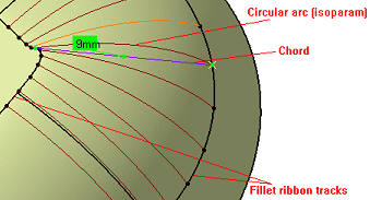
- The chord length is measured using the U isoparams (circular arcs)

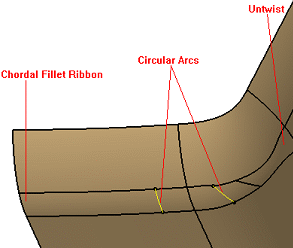
- The fillet surface respects the specified chord length. The chord length is measured using the
circular arcs.

- Some faces are created to correct the twists. In such cases a warning message is displayed. Such untwist surfaces in general do not satisfy the chord length constraint.