About the Circular Pattern.x Dialog Box | |||||
|
| ||||
Parameters
The Parameters box lets you choose the type of parameters, used to compute the location of the items copied.
| Parameters | Description |
|---|---|
| Instance(s) | Specifies the number of instances to be created. This number includes the original object. |
| Angular spacing | Specifies the angular spacing between consecutive instances. |
| Total angle | Specifies the total angle to be used, to place all the instances. The total angle is the sum of angular spacing between individual instances, from the first instance through the last instance. |
These parameters are:
- Instances & total angle: The app computes the angular spacing on specifying the number of instances and the total angle value.
- Instances & angular spacing: The app computes the total angle on specifying the number of instances and the angular spacing.
- Angular spacing & total angle: The app computes the number of instances on specifying the angular spacing and the total angle.
- Complete crown: The app computes the angular spacing between the instances. The total angle is considered to be 360 degrees
- Instances & unequal angular spacing: Distinct angular spacing can be assigned between each instance.
If you set the Instances & total angle or the Angular spacing & total angle parameters, you cannot define the total angle using formulas.
Reference Direction
To define a direction, you can select an edge, a line, a planar face or a plane. After selecting an edge, a line or a planar face, if necessary, you can also select a point to define the rotation center. If you select a plane, selecting a point is mandatory.
Contextual commands creating the reference elements you need are available from the Reference element box:
- Create Line: For more information, see Generative Shape Design User's Guide: Creating Wireframe Geometry: Creating Lines.
- X Axis: The X axis of the current coordinate system origin (0,0,0) becomes the direction.
- Y Axis: The Y axis of the current coordinate system origin (0,0,0) becomes the direction.
- Z Axis: The Z axis of the current coordinate system origin (0,0,0) becomes the direction.
- Create Plane: For more information, see Generative Shape Design User's Guide: Creating Wireframe Geometry: Creating Planes.
If you create any of these elements, the app then displays the corresponding icon next to the Reference element box. Clicking this icon enables you to edit the element.
Keeping Specifications
Selecting Keep specifications creates instances with the Up to Next (Up to Last, Up to Plane or Up to Surface) limit defined for the original feature. When limiting surfaces are not planar, consequently instances have different lengths.
Important:
|
Circle Spacing
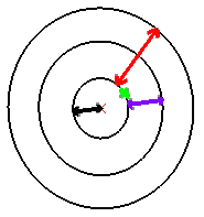
This figure will help you define your parameters:

| Representation | Parameter |
|---|---|

|
Feature to pattern |

|
Distance between the feature and the rotation axis |

|
Circle spacing |

|
Crown thickness |
Rotation of Instances
The Radial alignment option allows you to define the instance orientations.
If the option is selected, all instances have the same orientation as the original feature.

If the option is
cleared: all instances are normal to the lines tangent to the circle. 
Pattern Representation
Click ![]() to lighten the pattern's geometry. The instances are then represented with dashed
lines during the pattern definition and are no longer visible after validating the
pattern creation.
to lighten the pattern's geometry. The instances are then represented with dashed
lines during the pattern definition and are no longer visible after validating the
pattern creation.
This option is particularly used for patterns including a large number of instances.