About the Rectangular Pattern | |||||
|
| ||||
Rectangular Pattern Parameters
The Parameters list lets you choose the type of parameters, used to compute the location of the items copied.
| Parameters | Description |
|---|---|
| Instance(s) | Specifies the number of instances to be created. This number includes the original object. |
| Spacing | Specifies the spacing between consecutive instances. |
| Length | Specifies the total length to be used, to place all the instance. This length is the sum of the spacing between individual instances, from the first instance through the last instance. |
These parameters are:
- Instance(s) & Length: Lets you define the number of instances and the total length of the pattern.
- Instance(s) & Spacing: Lets you define the number of instances and the spacing between consecutive instances.
- Spacing & Length: Lets you define the spacing between consecutive instances and the total length of the pattern.
- Instance(s) & Unequal Spacing: Lets you define the number of instances and distinct spacing between instances.
Reference Direction
You can select an edge or a planar face to define the direction.
You can right-click the Reference element box and select any one of the following options.
- Insert Wireframe > Create Line: Creates a line. For more information, see Generative Shape Design User's Guide: Creating Wireframe Geometry: Creating Lines.
- Insert Wireframe > X Axis: Defines the X axis of the current coordinate system origin (0,0,0) as the direction
- Insert Wireframe > Y Axis: Sets the Y axis of the current coordinate system origin (0,0,0) as the direction
- Insert Wireframe > Z Axis: Specifies the Z axis of the current coordinate system origin (0,0,0) as the direction
- Insert Wireframe > Create Plane: Creates a plane. For more information, see Generative Shape Design User's Guide: Creating Wireframe Geometry: Creating Planes.
If you create a line or a plane, the corresponding icon is displayed next to the Reference element box. You can click the icon to edit the element.
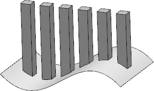
Keep Specifications
You can select the Keep specifications check box to create instances by using the Up to Next , Up to Last, Up to Plane, or Up to Surface limit defined for the original feature.
For example, the limit defined for a pad, that is, the Up to surface limit, applies to all instances. If the limiting surface is not planar, the instances will be set to different lengths.
Important:
|
If you create a pocket and a hole that overlap and you want to create a pattern of the hole, then the following scenarios are possible.
- Select the Keep specifications check box to create
the following pattern.

- Clear the Keep specifications check box to create
the following pattern.
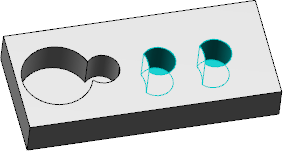
If you have created two overlapping pockets and you want to create a pattern of the pocket, the complete circular profile is created independent of the state of the Keep specifications check box.
Simplified Representation
Under Layout options, click  to lighten the
pattern's geometry. The removed instances are represented as dashed lines and are
not visible after validation.
to lighten the
pattern's geometry. The removed instances are represented as dashed lines and are
not visible after validation.
This feature is used in removing instances from large patterns.
again to cancel
the selection of this option, once the design is completed.Position of Object in Pattern
You can define the position in which you want to place the original object in the first and second directions. You can enter the position numbers for the first and second directions in the respective tab's Position boxes.
- You can create symmetrical distributions only if the number of instances is an odd number.
- If you change the number of instances of a symmetrical
distribution, instances are added or removed in the originally defined
direction. The position of the original object is retained. Therefore, the
original object will no longer be present at the center of the pattern.
For example, if you create a symmetrically distributed pattern with five instances, the original object is placed in the third position. If you increase the number of instances to seven, two new rows of instances are added in the defined direction and the original object is retained in the third position. Hence, the pattern will no longer be symmetrical.