About ISOGEN Integration

The Piping & Tubing 3D Design app can output your piping/tubing designs in a format suitable for use with ISOGEN software. This section explains what you need to know to understand this output format.

This page discusses:

ISOGEN

ISOGEN is a software product for drawing isometric piping designs.

Your Piping & Tubing 3D Design app includes support for ISOGEN in the form of Piping Component Files (.pcf) which can be read by ISOGEN, therefore allowing integration of your work with the ISOGEN product.

When the ISOGEN command is launched from the context toolbar, the Piping & Tubing 3D Design app:

  • Creates a .pcf file based on mapping tables which map piping/tubing design attributes to the equivalent ISOGEN attributes.
  • Optionally, this .pcf file is then sent to an ISOGEN utility software, I-run.exe, which transforms the .pcf file into a .dxf file.
  • Finally, the .dxf file can be imported back into your session as a new drawing.
Note: To generate the .dxf file you will need the ISOGEN utility software, I-Run.exe, and an appropriate license from Alias Ltd.

Mapping Tables

Mapping tables are used to convert your piping/tubing design attributes to the equivalent ISOGEN attributes.

The mapping tables are used to determine which ISOGEN symbol to place in a 2D drawing for a given 3D part. They are also needed to map attributes, and display information in a drawing.

This application comes with sample tables that contain the mapping needed for the sample parts provided. However, if you build new parts, or create new attributes, then you need to modify the mapping tables accordingly.

The sample mapping table files are located in ..\win_b64\startup\EquipmentAndSystems\Piping\DesignRules

The mapping tables must be set up and assigned to the Piping/Tubing Design Resources by the Piping & Tubing 3D Design app administrator.

For more information about the resource files, see [insert link: FluidicInfraDoc/SystemResources.doc/src/system-m-ad-ResourceFiles-sb.xml].

Extract and write the 3DEXPERIENCE Passport identifier in PCF files

To activate this capability, add 3DEXPERIENCE-PASSPORTID string in the AttributeName column for the pipeline miscellaneous isogen attribute ATTRIBUTEXX in the Attribute mapping table.

Piping Component File (.pcf)

ISOGEN .pcf files are text files which contain component and routing information.

For each component, there are various mandatory records which typically define:

  • Type (flange, pipe, valve, etc.).
  • Coordinates and size of the end-points.
  • Shape (SKEY), which is used to represent the component on an isometric drawing. For more information about the list OF SKEY managed by the app, see List of SKEY

From this component and routing information, ISOGEN lays out the piping isometrics and dimensions, and tabulates the bill of materials.

The .pcf file contains three sections:

Section Contains information about
Header Units, Line ID, spool etc
Component Mandatory component attributes
Materials Material, Quantity, etc.

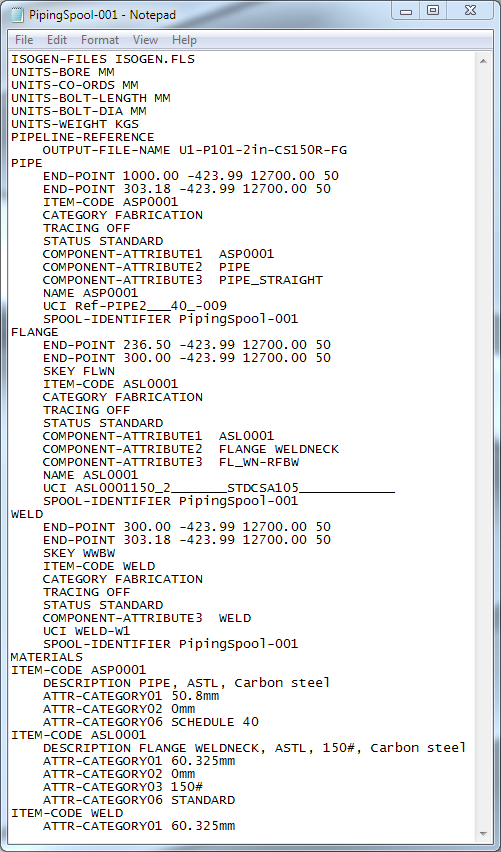
Typical .pcf File

An example of a typical .pcf file:


.pcf File Location

The .pcf file generated by the ISOGEN command is saved in a location specified by the Piping & Tubing Design apps administrator.

Orientation angle to be exported on PCF

If the user defines "DS_Fluid_Reference_Axis", all the orientation angle allowing to decide the Direction, Spindle direction, flat direction and its angle will be computed based on this reference axis.

"DS_Fluid_Reference_Axis" is the name of an axis system. It must be created inside the representation of the piping object.

Generate Tapping port information

The TAP connection is generated in the PCF file if a Port with a Flow Direction attribute is set to No-Direction in the Piping Part.

Depending on the part type, the Tap Port information is generated in two different ways:

Part Type Tap Connection Information in the TAP Connection
Tap Connection to Multi-Legged components TAP BP
  1. Tap port location according to the part. That is, Center point, End Point1, End Point2 or Branch Point.
  2. Tap port coordinates
  3. Tap port Nominal size
TAP Connection to components not Multi-Legged TAP
  1. Tap port coordinates
  2. Tap port End Style