Modifying Route Length | |||
| |||
-
Double-click a route.
You switch to the Piping & Tubing 3D Part Design app and a yellow symbol appears on each node of the route.
-
Click next to the end node of the segment you want to modify the
length.
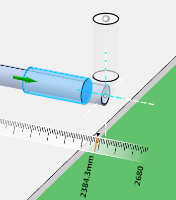
The 3D Manipulator appears and the last active manipulator is displayed.
-
Press the
A key until the Length Manipulator is
selected.

Note: If the node is the last node of the route, the Length Manipulator is directly activated. -
From the
Length Manipulator panel, select the options and
enter the values of your choice:
Option Description Snap Step Graduation value displayed on the ruler Skin Offset Distance value from the skin of the route Center Offset Distance value from the center of the route Offset Mode  Skin Offset: the offset is the distance
between the route and the skin of the other route.
 Center Offset: the offset is the
distance between the route and the center line of the other route.
 Auto Offset: if you select a line, the
Center Offset mode is used. If you
select a plane, the
Skin Offset mode is used.
Length Mode  Spool Length Mode: distance between two
nodes
 Straight Length Mode: distance of the
straight portion of a segment
Orientation  Orient with Local Axis: the white dashed
lines are oriented according to the local axis.
 Orient with Global Axis: the white
dashed lines are oriented according to the global axis.
Note: In case of port routing, if the Maintain Straight Route from Port option in Me
 > Preferences
is clear, then the port alignment is used to orient the white dashed lines.
 Orient with Robot Axis: the white dashed
lines are oriented according to the orientation of the
Robot.
Lock Direction  Lock Angle while Moving: the two extremity
nodes of the current segment are maintained along the direction of
the two adjacent segment.
 Unlock Angle while Moving: the direction of
the adjacent segments are modified.
Unlock Angle while Moving: the direction of
the adjacent segments are modified.Slope Mode  Slope Unset: the slope mode is not
applied.
 Slope Set: a slope is applied.
The
Slope Angle and the
Slope Percent options are available.
According to the slope value, the four horizontal dashed lines are inclined.
Slope Angle Slope value with an angle value. Positive and negative values are available.
Slope Percent Slope value in percentage. Positive and negative values are available.
-
To modify the length of the segment, do one of the following:
- Drag the Length Manipulator.
- Edit the ruler value. To quickly access the ruler value, press the Space key, enter a value and press Enter.
- Select a surface or the "wings" of the robot, a line or an axis of the robot, or a point to route until this surface or line. In this case, the Offset Manipulator command is launched. For more information, see Routing with the Offset Manipulator.
- Select a part. Five symbols are displayed: the two ports, a computed node that appears only if two routes intersect and represents the intersection of the route directions, and two arrows that indicate the direction of the port. If you select one of the ports or the computed node, the behavior is similar to 3D point selection. If you select the one of the arrows, the behavior is similar to line selection. The length of the route is modified consequently.
Notes:If you modify the length of a route from a port, a directional point is automatically created if the option has ben selected in Me
 > Preferences. The directional length on extremity port is taken into account to
manage a minimum straight length.
 You can select the robot only when it is put on design, and not on the default position, where the selection changes the point of view.