When customizing the xml do not change the format of the xml.
Plates
- ThicknessOrient
- The side of the support on which plate thickness is oriented.

Stiffeners

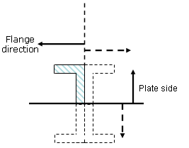
- PlateSideOrient
- The side of the plate on which the stiffener is placed .
- SectionOrient
- Orientation of the stiffener flange.
- AnchorPoint
- The point at which the stiffener section is anchored along its trace.
Stiffeners on Free Edge
- AnchorPoint
- The point at which the stiffener section is anchored along its trace.
Symbols Used
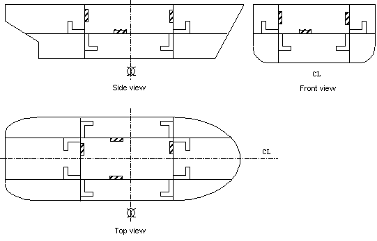
The following is a list of orientations that can be used to specify molded conventions.
Symbols used for orientations (ThicknessOrient of plates, PlateSideOrient and SectionOrient of stiffeners).
- HP
- Horizontal plus. Nls name : Top.
- HM
- Horizontal minus. Nls name : Bottom.
- LP
- Longitudinal plus. Nls name:
- Portside, if FrontOrientation = Xp in the project parameters file (Front of the ship correspond to X+ ).
- Starboard, if FrontOrientation = Xm in the project parameters file (Front of the ship correspond to X- ) .
- LM
- Longitudinal minus. Nls name:
- Starboard, if FrontOrientation = Xp in project parameters file.
- Portside, if FrontOrientation = Xm in project parameters file.
- LI
- Longitudinal inboard. Nls name: Inboard.
- LO
- Longitudinal outboard. Nls name: Outboard.
- NR
- Normal of support plane.
- IV
- Inverted normal of support plane.
- TP
- Transversal plus. Nls name:
- Fore, if FrontOrientation = Xp in project parameters file.
- Aft, if FrontOrientation = Xm in project parameters file.
- TM
- Transversal minus. Nls name:
- Aft, if FrontOrientation = Xp in project parameters file.
- Fore, if FrontOrientation = Xm in project parameters file.
- TI
- Transversal inboard. Nls name: Inboard
- TO
- Transversal outboard. Nls name: Outboard
- OtherI
- Other Inboard. Nls name:
- Inboard for shell plates or shell stiffeners
- Normal for plates using Other category (this orientation corresponds to the normal vector of the support used to create the plate)
- OtherO
- Other outboard. Nls name:
- Outboard for shell plates or shell stiffeners
- Invert for plates using Other category (opposite of the normal vector)

Anchor Point Definition
- StiffenerClass Name
- The name of the object.
- DefaultAnchorPoint
- The default anchor point you get when placing the object.
- AnchorPoint Name
- The anchor points that are available in the Anchor Point box in various dialog boxes. Each anchor point should be entered on a separate line, as shown below.
Following are the values that can be used to define DefaultAnchorPoint and AnchorPoint Name:
- catStrBottomLeft
- catStrBottomCenter
- catStrBottomRight
- catStrCenterLeft
- catStrCenterCenter
- catStrCenterRight
- catStrTopLeft
- catStrTopCenter
- catStrTopRight
- catStrGravity
- catStrWebSideLeft
- catStrWebSideRight
- catStrWebCenter
- catStrWebCenterLeft
- catStrWebCenterRight
2D View Orientation
- Orient2D_U
- Orientation in the U direction.
- Orient2D_V
- Orientation in the V direction.
The valid values you can enter are as follows:
- XP
- X plus
- XM
- X minus
- YP
- Y plus
- YM
- Y minus
- ZP
- Z plus
- ZM
- Z minus
- NA
- Not applicable (orientation attribute ignored. Example, orientation does not apply to shell plates.)


