Plastic Mesh Setup | ||||
|
| |||
Mesh Size
You can adjust the average mesh size used throughout the plastic part.
Boundary Layers
Most plastic meshes use thin boundary layer elements near the cavity walls, with larger elements toward the center where conditions are more uniform. This approach allow more accurate resolution of temperature and solidification effects that vary through the thickness of the part, because the surface layers freeze while the central layers continue to flow.
For a simple part of uniform thickness, the default mesh parameters are selected to create five elements through the thickness of the part, which provides a reasonable balance of accuracy and computational cost.
Simplify Geometry Under
You can ignore small edges to simplify the mesh. Whenever possible, edges are merged if the topological edges are smaller than the specified value or if the distance between two edges is less than the specified value.
In the following example, the mesh is simplified (in the middle image) when the specified value is less than the distance between the parallel edges. On the right side, the mesh when the value is greater than the distance between the parallel edges.


Remove Logos
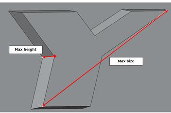
You can ignore protruding features like logos when you create the plastic part mesh. Logos are not considered for removal if they protrude more than the maximum height you specify or if the diagonal measurement of the size exceeds the specified maximum size.
