-
Create a logical reference and insert a symbol representation under the reference.
-
Double-click the symbol object to edit the symbol representation in Symbol Design.
-
Create an on-sheet or an off-sheet symbol.
-
Create a text template. For more information about the creation of text templates, see
Creating Texts.
Note:
If no connection point exists within the symbol, a connection point is automatically
created at the origin ordinate of the on-sheet symbol.
-
In the Link Template
dialog box, define a link template:
-
In the Package box, select Piping and Tubing Logical.
-
In the Type box, select Logical Pipe.
- In the PLMEntity box, select Title.
- Click Insert.
-
In Data Setup, create a new resource set in Diagram Resources.
-
Assign the logical reference to the On Sheet Symbol for Same Sheet Context resource.
- Optional: Define the following criteria:
- Routable Type: Associates a type of route line to your sheet connector representation.
- Default: Defines the representation as the default one.
- In the diagram view, route the first part of your pipe with an on-sheet connector.
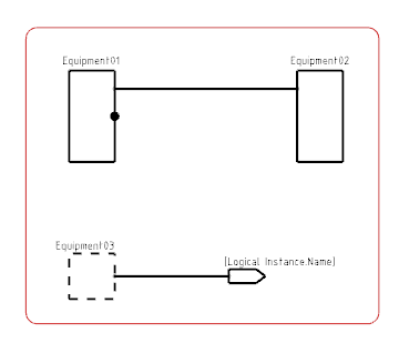
Note:
The first symbol to be inserted is always the off-sheet symbol. If the second symbol is placed on the same sheet, the symbol of the first sheet connector is updated with the on-sheet symbol.
- Route the second part of your pipe with an on sheet connector.
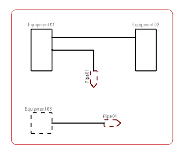
The text applied to the symbols appears in the diagram view. Both sheet connectors symbols display the attribute of the logical pipe.
|