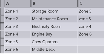
You can create a schematic zone as follows:
- Draw a parentless zone inside or outside any parent zone
- If a parent zone is defined in the sheet, draw its child zone inside
- If a parent zone is not defined in the sheet, draw its child zone outside any
other zones
Note:
The zone names are displayed according to what is defined in the Zone Names resource .
-
Double-click the diagram view.
The diagram view is active.
-
From the Layout section of the action bar, click
Create Zone
 .
.
Your pointer turns into a red cross.
-
Click in the diagram view to define the starting point of your zone.
-
In the context toolbar, select one of the following options:
-
According to the option selected, perform the following actions:
| Option | Delimiting the zone |
|---|
Lines  |
Click the diagram view to place all the points delimiting the
zone, and then press the Enter key. |
Rectangle 
|
Enlarge the geometry to create your zone, and then
click. |
Note:
To modify the schematic zone, click it and select  on the context toolbar.
The Create Zone dialog box
appears.
-
Select the desired category from the Zone category
list.
-
In the Zone name list, select the desired zone.
-
Click OK.
Notes:
- The name of the schematic zone displayed in the Properties
cannot be modified.
- If you modify manually the zone description in the Properties,
it is no longer possible to retrieve automatically the
description from the Data Setup. You must delete the zone and
create it again.
- For each created zone, you can set an
automatic text through the Diagram
Resources resource set. For more information,
see About Schematic Zones.

 .
.