Opens the interference simulation or interference metric in an authoring tab.
By default, this check box is selected.
Work in navigation tab
Opens the interference simulation or interference metric in a navigation tab.
Geometries
None
Select this check box to hide all interference geometries.
Main interference type
Select this check box to display interference geometries corresponding to
the interference system status.
By default, this option is
selected.
All clashes, contacts or clearances for each interference
Select this check box to compute and display the intersection curves
corresponding to the clash zones, the contact zones, or the clearance
zones at the same time when analyzing interferences.
By default, this check box is clear.
Notes:
If clearances are displayed with triangles, for each group of
connected clearance triangles, a minimum distance value is
displayed in the work area.
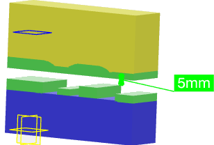
If clearances are displayed with areas, only a single minimum
distance value is displayed in the work area.
Clash
Lets you specify how the clashes must be displayed in the work area. You can display the clash curve, clash volume, or clash curve and
volume.
By default,
Curve and volume is selected.
Clearance
Lets you specify how the clearances must be displayed in the work area. You can display the clearances with triangles or area.
You can
specify the accuracy value to use while displaying the area. By default,
accuracy value is 10 mm.
When Clearances are Displayed with
Triangles
When Clearances are Displayed with
Area
By default,
Triangles is selected.
Quantifiers
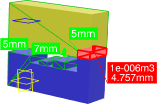
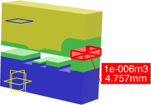
Penetration vector
Select this check box to compute and display the penetration vector and the
numeric value in the work area.
By default, this check box is selected.
Clearances
Select this check box to compute and display the minimum distance for
clearance.
By default, this check box is selected.
Interfering Parts
Color According to Instance
You can choose colors for the parts in an interference. These colors are
applied when analyzing parts.
By default,
: Indicates first instance
: Indicates second instance
Color According to Interference
Select this option to apply colors to the interfering parts depending on
their interference type.
: Represents clashes
: Represents contacts
: Represents clearances
Transparency
Applies transparency to interfering parts.
When set to 0, interfering parts are opaque. When set to 255,
interfering parts are completely transparent.
By default, the transparency values is 128.
Interference Icon
Display Interference icon in 3D area
Select this check box to display icons in the work area to denote interferences.
Customized Display
Display customize instance names in multi list using Business Logic
Select this check box to display customized instance names in the
interference simulation multi list using business logic.
Display tooltip
Display tooltip for multi list
Select this check box to display tooltips for instances in the
interference simulation multi list.
 By default, this check box is selected.
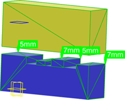
 : Indicates first instance
  : Indicates second instance
  : Represents clashes
  : Represents contacts
  : Represents clearances