Wireframe and Surface | ||
| ||
Global
Allows you to define specific preferences for small-range, normal-range, and large-range parts.
Tolerant Modeling (Default values at creation)
| Warning: The following options are only available with the Generative Shape Design product. |
Select the required option:
- Input parameters
- Merging distance
- This option defines the distance below which elements are to be joined, healed, or
extracted.
Warning: - This option is available with the following commands: Join, Healing, Extract, and Multiple Extract.
- Extract and multiple extract commands have a particular behavior: refer to the corresponding chapters to have further information.
 By default, This option is set to 0.001mm.
 - Tolerant laydown
- If the laydown of an input guide on a surface fails, you can select the Tolerant
laydown. When activated, a fixed lay down tolerance of 0.1mm
is applied.
Warning: - This option is available with the following commands: Parallel Curve, Sweep, Multi-Sections Surface, Blend, Split (surface by curve), Curve Smooth, Fill, and Extrapolate.
- Tolerant laydown only applies at feature creation. Therefore, if the option is not selected when creating the feature, selecting it afterward has no effect on the feature.
 By default, This option is selected.
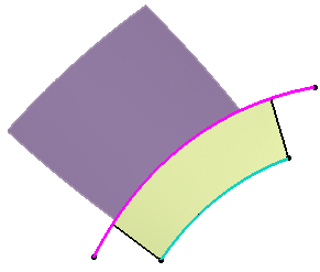
 Here is a scenario with the Sweep command.
-
Create a tolerant swept surface and define a Deviation from guide of 0.1 mm.
In our scenario, we created a swept surface using an implicit linear profile and the ''two limits'' subtype. We created Curve.1 (blue curve) and Curve.2 (pink curve) as the guide curves.

-
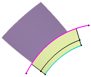
Create a parallel curve of Curve.1 using the swept surface as the support.
The creation of the parallel curve fails and an error message opens informing you that the guide curve does not lie on the swept surface and advise you to project it onto the support.
Select the Tolerant laydown option.
Perform step 2 again.
The creation of the parallel curve is successful.

Warning: It is advised not to use a wire that lies on the edge of the sweep when working with the Tolerant laydown option.
- Output parameters
- Continuity Types
- Three continuity types are available:
- None: deactivates the smoothing result.
- Tangency: enhances the current continuity to tangent continuity.
- Curvature: enhances the current continuity to curvature continuity.
 By default, The option is set to
None.
 Warning: This option is only available with the Project and Parallel Curve commands. - Maximum deviation
- This option enables you to set the allowed deviation between the initial element and the
smoothed element by entering a value or using the spinners.
 By default, This option is set to 0.001mm.
 Warning: This option is available with the following commands: Project, Parallel Curve, Sweep, Multi-Sections Surface, and Curve Smooth. For the Sweep and Multi-Sections Surface commands, only the Deviation parameter can be defined from Tools > Options (the Angular correction parameter cannot be defined here). The Deviation and Angular correction is activated only if the smoothing type is set to Tangency or Curvature.
Axes Visualization
- Axes visualization limited to the bounding box of the input
- Clear this option to visualize an infinite axis in the 3D geometry.
![]() By default, This option is selected.
By default, This option is selected.


Groups
- Integration of created features as group inputs
- Select this option if you want each new feature to be included as an input in an existing
group and remain visible in the specification tree.
If you clear this option, the created features are not be included in the group and are hidden in the group tree (expand the group to be able to see it).
 By default, This option is cleared.
For further information, see Managing Groups.Warning: - This option is only available when creating a new feature.
- It is only available for features accessible in the Generative Shape Design workbench. All other features are not included in the group even if the option is selected.
Stacked Analysis
- Stacked analysis default behavior set as temporary
- Select this option to automatically create a temporary analysis when verifying connections between surfaces or curves.
![]() By default, This option is cleared.
By default, This option is cleared.
| Warning: This option is only available with the Offset command. |
Contextual Menus
- Contextual menu on one level
- Generative Shape Design commands available from a contextual menu from the dialog box options.
For example, the commands that can be applied to the current selection, are
sorted in a list with sublevels. Select this option to get the commands in a
one-level list.
 By default, This option is cleared.
Dialogs appearance
- Use Dialogs with new appearance