Material Removal | ||
| ||
Behavior
- Touch is collision
- When selected, detects collisions of type touch (or contact).
 By default, this check box is selected.
 - Multiple material removal simulation result on program
- When selected, stores material removal simulation results on more than one
operation in the program.
 By default, this check box is cleared.
 - Set a limit on the collision detection number during the simulation
- When selected, limits the number of saved stocks during stock clash detection in
simulation, once the number you set is reached.
 By default, this check box is cleared.
Accuracy
The accuracy values can be set are taken into account for all material removal simulation apps.
The accuracy value set has a direct bearing on the performance of a simulation. There is a trade-off to be made between accuracy and performance. Using a low tolerance generates many more faces on the stock and tool. This increases accuracy, but takes more memory and the simulation is slowed down. Using large tolerance generates fewer faces on the stock and tool. This takes up less memory, so the simulation is faster but accuracy is reduced.
- Milling accuracy
-
Milling accuracy corresponds to the tool tolerance. During simulation, tools are represented as faceted solids, approximating the real tool shape. The accuracy with which they do so is known as the tool tolerance. This tolerance defines the maximum distance by which faceted tool representation deviates from the actual tool geometry. Thus a small value for the tolerance will result in a more accurate, and so more finely faceted, tool representation.
- Manual: Set the tolerance value manually. The minimum value is 0.001mm.
- Machining operation tolerance: Uses the tolerance set on the machining operation
- Automatic: Tolerance is optimized proportionally to the tool radius.
Performance
- Tool and faceting
- Select the required method of
tool faceting used in material removal simulation. The number of facets for
a tool representation is determined by the chord deviation that is set for
the tool diameter (0.005% of the tool diameter).
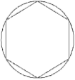
- Smaller: The picture shows a rough
approximation of a tool with six facets. This is the default
value.

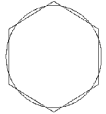
This is the most accurate method for the Arc through Three Points command.Note: The chord deviation is always inside the actual circle, and the points are always on the circle (accurate). - Standard: The picture shows a rough approximation of a tool with
six facets.

This is the fastest, but less accurate method for material removal simulation. However, it is not suitable for the Arc through Three Points command.Note: The chord deviation is partly inside and partly outside the actual circle, and the points are not always on the circle.
 By default, this check box is selected.
 - Smaller: The picture shows a rough
approximation of a tool with six facets. This is the default
value.
- Tool axis interpolation angle (5-axis only)
- Select the maximum angle variation of the tool axis that is allowed between
two consecutive points.
- Best performance is obtained for an angle of 10 degrees.
- Decreasing the angle improves the precision of the simulation. However, this requires increased memory and computation time.
This angle is set to 1 degree.
Color of Tool and Machined Area
- By Tool
-
When selected, defines a color for each tool and machined surface. The colors can be defined as:
- Same: same color for all tools.
- Last tool different: different color for the last tool.
- All different: different color for each tool.
- Defined on the tool: color as defined in the tool resource, during material removal simulation.
Note: Best performance is obtained with same colored tools. - By Feedrate
- When selected, proposes six specific values of feedrate.
- You can modify these feedrate values.
- You can choose a color for each feedrate interval. For example:
- For Feedrate <= 100mm_mn, the color is green.
- For Feedrate <= 500mm_mn, color is yellow.
 By default, this check box is cleared.
Positioning Move
- Maximum tool axis variation
- Set the maximum tool axis variation allowed
between the end point of an operation and the start point of the next
operation. Note: If the tool axis varies by an amount greater than the specified value, the tool is positioned at the start of the following operation. This angle is set to 1 degree.