General | ||
| ||
Default type for plate limits
This area displays the following structural objects on which you can define the default limit type:
- Plate
- Standalone Plate
For these structural objects, you can define the default limit type such as Short Point, Long Point, and Weld using the corresponding lists.
 By default, the limit type for plate and standalone plate is set as Weld.
Default type for profile limits
This area displays the following structural objects on which you can define the default limit type:
- Stiffener
- Stiffener on free edge
- Member
For these structural objects, you can define the default limit type such as Short Point, Long Point, Weld, Metal to Metal, Miter, Web Weld, Flange Weld, and Limit Trace using the corresponding lists.
By default, the limit type for stiffener, stiffener on free edge, and member is set as Short Point.
Forming mode
This area displays the following forming modes for openings and slots:
- Molded Form
- The opening contour is projected on the molded surface of plate.
The projected contour is then extruded in the direction normal to the molded
surface. This forming mode prevents bevel creation.
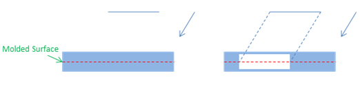
- Boolean
- The opening contour is extruded along the direction. The opening
is created by using the Boolean operation. This forming mode may create bevels.
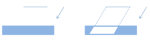
- Clash Free
- The opening contour is projected on both the faces. The faces are
modified to ensure that the extrude contour along the direction is never in
clash with the penetrated object. This forming mode prevents bevel creation.

By default, Molded Form is selected.
Profile sub-element selection
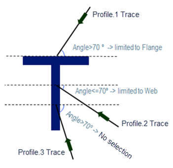
Sets the angle for automatically selecting the profile sub-elements as limit. For angle less than or equal to the defined angle, the web face is automatically selected as the profile limit. This defined angle is the angle between the trace directions of the limited and limiting profile. If the angle between the traces is:
- Less than or equal to the defined angle, the web face is selected as the limit.
- Greater than the defined angle, the flange face is selected as the limit.
| Warning: If the angle is greater than the defined angle at the limiting profile side, neither the profile nor its sub-elements are selected as limiting element. |
Automatic naming
- Use automatic naming upon object creation
- Activates the Automatic Name option by default when creating a new object. By default, this check box is selected.
- Force execution of naming rule in the Reset Action Rule command
- Executes the naming rule even when you click the Reset Action Rule contextual command.
Automatic limit mode
- Default automatic limit mode for profile
- This list lets you select the default limit mode for creating a profile. It contains the following limit modes:
- Border: New planes are created at the intersections of the profile with the boundary of the panel . These planes are then selected as limiting elements for the profile.
- Structure: The limits of the panel are retrieved and used for the profile.
- Manual: The profile is created without limits. You can manually specify the limits.
By default, Border is selected.