About the Adjust Layout | ||||
|
| |||
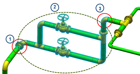
The Adjust Layout command enables you to move a network of fluidic elements. This network is connected to other fluidic elements. There are x border connections to the parts of the network which remain fix. The aim of the Adjust Layout command is to apply the right behavior on each border connections between the part of the network you want to move and the fix parts of the network.
The following image is an example of a network with where 1 and 3 are the border connections between the moving network and the fix parts, and 2 is the part of the network that needs to be moved.
As many types of border connections can exist, the following table explains briefly the behavior for each use case.
| Not selected object \ Selected object | Rigid Route | Part | Rigid route with branch |
|---|---|---|---|
| Rigid route | Stretch segment | Stretch segment With the Stretch Segment option, if the part is an elbow, a rotation is applied to avoid the creation of a new bend. | Stretch segment With the Stretch Segment option, the direction of the branch port is updated to avoid the creation of a new bend. |
| Part | Stretch segment With the Stretch Segment option, if the part is an elbow, a rotation is applied to avoid the creation of a new bend. | Disconnection | Stretch segment |
| Rigid route with branch | Stretch segment With the Stretch Segment option, the direction of the branch port is updated to avoid the creation of a new bend. | Stretch segment | N/A |
- Segment mode: if you select the Create Segment option, one point can be created.
- Direction mode: if you select the Keep Direction option, the bend node follows the direction of the previous segment.
- Translation direction: both previous options depend on the translation direction.
For flexible routes, the shape is updated with the new position of one of the end segments. The Segment and Direction modes have no impact on the new shape.
If the border of the selected subpart network is a cut elbow or a route bend and if the next bend is also a cut elbow or a route bend, a slope behavior is applied: all objects between the two bends remain aligned after the translation of the selected subpart network.
The Adjust Layout is performed in four main steps: selection of the subpart of the network you want to move, selection of the reference point on this network, definition of the direction and selection of the target of this translation. Following the type of connection between the sub part of the network that moves and the remaining network, the behavior is different (stretching of the route, creation of new nodes, disconnection,..)
The selection of the subpart network is very important because the translation is applied only on the selected objects and the border objects are adjusted to keep or not the connection with the fix network.