Routing with the Offset Manipulator | |||
| |||
-
Double-click a route.
You switch to the CATIA Rebar Routing 3D Design app and a yellow symbol appears on each node of the route.
-
Click next to a node.
The 3D Manipulator appears and the Bend Manipulator is activated.
-
Press the
A key to activate the Length Manipulator.
Note: If the node is the last node of the route, the Length Manipulator is directly activated.
-
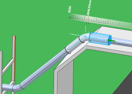
Select a point, a line, a surface, or the handles of the Robot.
The length of the segment is modified and the node is aligned with your selection.
The following images show you the behavior of the route when selecting the line displayed in red:


Note: The orientation of the 3D Manipulator preview is predictable and takes into account the location of the point, line, or plane selection. The 3D Manipulator preview is oriented in the direction of the selection. -
In the
Offset Manipulator panel, select the options
and enter the values of your choice to adjust the position of the node:
Option Description Skin Offset Lets you enter a skin offset.
You can specify a positive or negative offset.
Press I to invert the offset value:
- From a positive to a negative offset
- From a negative to a positive offset
Note: The offset does not take into account the orientation of the route. The direction in which you create the route always involves a positive offset.Center Offset Lets you enter a center offset. Offset Mode  Skin Offset: applies the offset value between
the skin of the main route and the other route.
Skin Offset: applies the offset value between
the skin of the main route and the other route.- Press Shift to switch between four
possible solutions proposed for the offset. The Skin
Offset proposes solutions for the external and
the internal sides of the route. Note: The four proposed solutions take insulation thickness into account.
- Press P to switch between three plane selection solutions.
 Center
Offset: applies the offset value between the center
of the route and the other route.
Center
Offset: applies the offset value between the center
of the route and the other route.Orient Mode  Local: orients the white dashed lines
according to the local axis.
 Global: orients the white dashed lines
according to the global axis.
Global: orients the white dashed lines
according to the global axis.Context Selection Mode  Move Node: updates the position of the node
based on the offset mode and the offset distance.
  Modify the Origin of the Rule: displays the
distance between the context selection and the selected node.
 Automatic : chooses between the
Move Node and Modify the Origin of the
Rule options automatically.
 If the new node position generates update errors while using the Automatic option, the Modify the Origin of the Ruler option is applied.
If there are no update errors, the Move Node option is applied.
Lock Direction  Activate: Moves the second point of the
current segment along the direction of the next segment to reach the
expected orientation.
 Deactivate: Moves the second point of the
current segment along the orientation of the current segment while
keeping the length of the current segment.
Deactivate: Moves the second point of the
current segment along the orientation of the current segment while
keeping the length of the current segment.Insulation Thickness Displays the clearance value to be applied around the route.
Safety Offset Mode  Include safety mode from table: creates a
safety offset around the current route based on the
Safety Offset value. The value that is
used comes from the first matching row of the Safety
Offset column in the Safety
Offset table. If:
Include safety mode from table: creates a
safety offset around the current route based on the
Safety Offset value. The value that is
used comes from the first matching row of the Safety
Offset column in the Safety
Offset table. If:- A line ID is set on the route, then the table is the one in the specification that is set on this line ID.
- No line ID is set on the route, then the table is the one in the Default Specification.
Note: If no specification is set on the route, then the Safety Offset value is ignored.For more information, see .
 Do not include safety mode from table:
ignores the Safety Offset value.
 Automatic: chooses automatically which
Safety Offset value to apply depending on
the context selection. If you select:
Automatic: chooses automatically which
Safety Offset value to apply depending on
the context selection. If you select:- A geometry, the Safety Offset value is the one from the current route.
- Another route, the Safety Offset values of the current route and of the selected route are compared. The Safety Offset that is used is the greatest value of the two.
Safety Offset Displays the safety offset to be applied around the route.
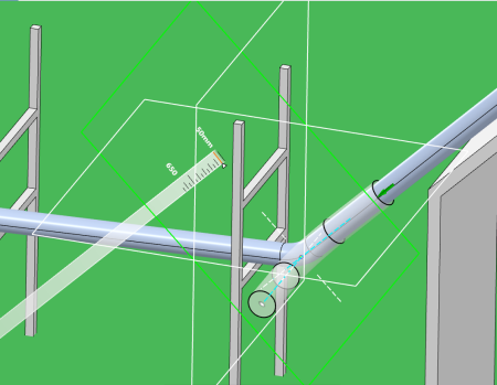
Note: In case of line selection, white rectangles can appear to show you different solutions following XY plane, ZX plane, YZ plane, and a last plane representing the shortest distance between the selected line and the direction of the segment. If the plane is normal to the direction of the segment, the rectangle is not displayed.