Creating Rebar Groups in Sketch Mode | ||||
|
| |||
-
Open a 3D Shape.

-
From the Reinforcement section of the action bar,
click Rebar Group
 .
.
-
To select the input rebar support, hover over a surface or an edge in the 3D area.
A blue plane appears under your cursor. Select a plane as support.
A contextual toolbar appears allowing you to choose a rebar group creation mode, to edit or isolate the plane and exit the command.
Command Description 
Sketch: Adds rebar layers with the creation of 2D profiles in a sketch. 
Template: Adds a rebar layer with a selected object type. 
Modifies the support plane. 
Edits the point of the plane. 
Isolates the plane. 
Exits the command. Notes:- If you select axis systems as input, a pattern selection is created.
- If a plane or a surface is selected, a linear pattern is created using the plane as pattern start and the solid extremum as pattern end.
- If an edge is selected, a plane perpendicular to this edge is created along with a curvilinear pattern, the edge being used as the pattern curve and the point of pick as the pattern start point.
- If you create a template rebar layer on a normal plane to a curve, a curvilinear pattern is created. The planes are not created on the solid that contains the plane, and default planes are created under another node in the tree.
- The Rebar Split and Multiple Split commands cannot be used on Rebar Groups.
- The pattern is editable.
-
To design a 2D layer profile, click Sketch
in
the contextual toolbar.
After validating your profile via the Rebar Profile panel and the Tools Palette, you can choose a configuration value. Each profile is used as a layer for a rebar group. In the Rebar Profile panel, you can:
- Set a Configuration diameter value on the profile to define the future layer. You can also modify it in the Rebar Group window as explained below.
- Remove the actual profile or all the profiles at initialization by clicking
 .
.
To edit a profile, double-click it in the tree. The Profile panel is displayed.
-
Click
 to create another profile or
to go back to the Concrete Structures 3D Design
app.
to create another profile or
to go back to the Concrete Structures 3D Design
app.
The Rebar Group dialog box appears, displaying the following commands:
Elements and Commands Description Support Name of the selected support (a surface or an edge). Note: If you select a surface as support: these buttons are replaced by Smart Plane allowing you to change the support selection.
Modifies the support plane. Edits the point of the plane Isolates the plane. Sketch: Adds rebar layers with the creation of 2D profiles in a sketch. Template: Uses the template of an object type for the rebar layer creation. For more information, see Creating Rebars by Group. 
Display Option: Hides or shows all the faces of a layer. 
Display Option: Appears in a contextual toolbar, pointing to the layer. Hides or Shows the shift label on the layer. Layer Properties Expand the Layer Properties section to check the bar sketch name and edit it by clicking  .
.Distribution Expandable section to check or edit the pattern information and use commands to delete  , edit
  or select
another pattern
or select
another pattern  (only
possible after the deletion of the existing one). For more information, see
the step below.
(only
possible after the deletion of the existing one). For more information, see
the step below.
Deletes a rebar layer. Name The name of the rebar layers created from a sketch or a template. Select a line to highlight the rebar layer in the 3D area. A Shift Options command appears in a contextual toolbar, pointing to the layer, and you can hide or show the shift label by clicking  in the
Rebar Group dialog box.
in the
Rebar Group dialog box.Type On the same support, you can create several rebar layers with the Sketch or Template mode. The Type column of the panel with the Sketch or
Template
icon indicates
the creation mode.Configuration Displays the diameter for the rebar layer. You can select another one in the list. To modify the rebar layer within the Rebar Creation command. Each profile is used as a layer for a rebar group.
-
To reinitialize the rebar group distribution, expand the
Distribution section and do the following:
The Distribution area containing pattern information and, commands to delete
, edit or
select another pattern (only possible after
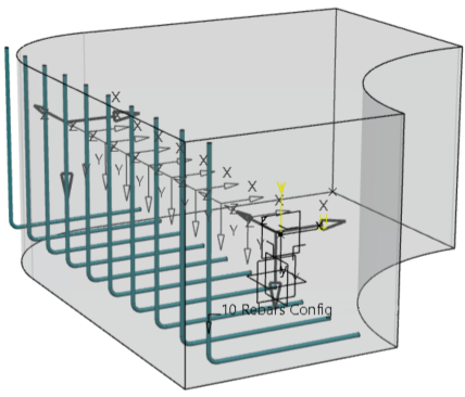
the deletion of the existing one). The linear pattern is chosen by default and it is defined in the Distribution text box. For example, if you type
10x300mm, the pattern will contain ten axis systems spaced by 300mm. The distribution text will be converted into pattern definition.The unit is set in Preferences: From the top bar, select Me
 > Preferences, and then click the Common
Preferences tab and expand the section.
> Preferences, and then click the Common
Preferences tab and expand the section. You can choose the Count or Spacing modes and, the active mode is indicated in the dialog box. For more information, see next step.
A list of a minimum of three rebars containing the pattern is displayed. Click
 to expand the list.
- Edit the text in the Distribution box, for example:
300mm+2x400mm+335mm, or3x300. The pattern will contain one axis system at 300mm, two axis systems every 400mm, and one more axis system at 335mm.With the textual distribution, it is no more necessary to edit the Pattern feature to modify or create Pattern Groups and their distribution. The general distribution text format is: C1 x S1 + C2 x S2 + C3 x S3.
"Ci": is the number of axis of the group "i". If the number of axis of this group is equal to 1, it can be omitted.
"Si": is the spacing length of this same group. It can be associated to a unit, or without unit. If it does not have unit, the unit set in Preferences is used. If a unit is used to define a length, the same unit must be used for all lengths
- Create Pattern groups: Points must be created/selected in the 3D area to split existing groups into two parts.
- When you initialize the rebar layer layout, there is only one group in the
pattern. The Count and Spacing modes can be changed with the combo box. If you click:
- Count
 : Only count
value modification and only one group are allowed.
: Only count
value modification and only one group are allowed. - Spacing
 : Only spacing
value modification and only one group are allowed.
: Only spacing
value modification and only one group are allowed. - Count and Spacing
 : Count
and Spacing values modification is allowed and several groups can be created. If a
Pattern end point is specified, a Limit Spacing option is
available to shift the Pattern distribution.
: Count
and Spacing values modification is allowed and several groups can be created. If a
Pattern end point is specified, a Limit Spacing option is
available to shift the Pattern distribution.
If the current mode is Count and spacing, it can contain as many groups as needed, separated by the plus sign. All the groups created are in the Count and spacing mode. There cannot be several groups with different modes. If you change the definition of one group, the text editor is grayed out. If a pattern end point is specified, a Limit Spacing option is available to shift the pattern distribution.
If a start and/or end offset values are defined, distribution is done between these boundaries. The start and end offsets are not managed in the text editor, edit the pattern by clicking
to modify their
values. - Count
- Click to launch the
pattern for more precise edition.
Click anywhere in the 3D area to validate the distribution text, and the preview of the Axis systems is refreshed. An error message may appear if the input distribution text is incorrect. The pattern distribution is reinitialized with this text. Then you can continue to edit the rebar layers.
- Edit the text in the Distribution box, for example:
-
To edit/move a rebar layer, especially when it intersects with another one in the 3D area, click it
in the Rebar Group dialog box and do one of the following:
-
Change the shift of the layer with the option called With
length by defining a numerical length value normal to the sketch plane.
And click Reverse
 to define the
shift side.
to define the
shift side.
-
Change the shift with the From selection option, by using
another layer as contact referential. The From selection is
highlighted to reveal the possible selection of a layer to move the first one. Click
Reverse to define the
shift side.
Before clicking Apply, you can visualize the first bar of each layer in the 3D area.
-
Change the shift of the layer with the option called With
length by defining a numerical length value normal to the sketch plane.
And click Reverse
-
Click Apply to compute the rebar layers.
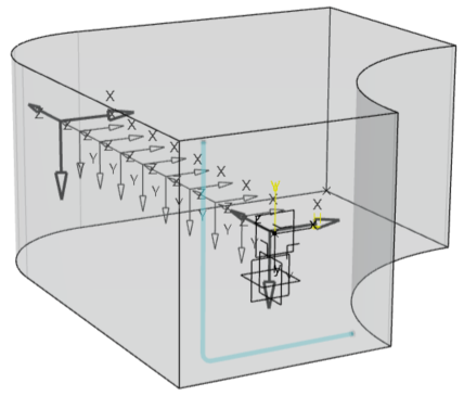
The rebar layers follow the pattern.
Each rebar layer is defined by a sketch profile, the pattern and the plane. In the tree, the Reinforcing bars Group Set contains a Geometry node aggregating the geometries of the rebar groups and the new sketch called Reinforcing bars Sketch.
In the tree, a Reinforcing Bars Group Set is created in which you can find:
-
A Reinforcing Bars Group Feature which contains a sketch, a point and a plane.
Important: The deletion of one of these elements deletes the rebar layers of the group. - n Reinforcing Bars Layers.
-