Creating a Plane Sensor | ||||||||
|
| |||||||
-
From the Setup section of the action bar, click Plane sensor
 .
The Plane sensor dialog box appears, and you are prompted to select a manufacturing cell where the sensor will be created.
-
Select the manufacturing cell.
In the work area, the compass is snapped at the origin of the initial plane.
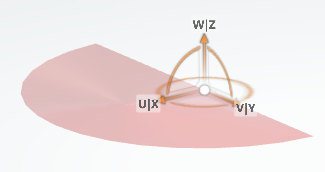
The Creation of plane sensor dialog box appears.
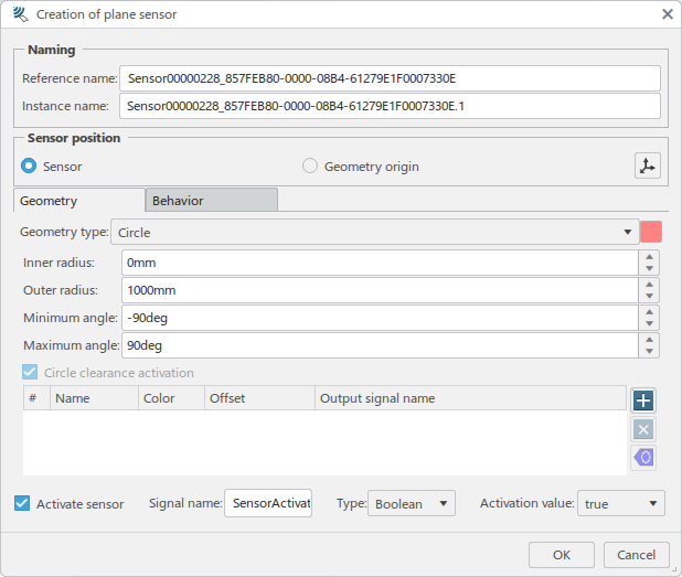
In the Creation of plane sensor dialog box, Reference name and Instance name are populated with default names. You can enter meaningful names for the sensor:

-
In the Sensor position section, you can define the context in
which position changes occur.

- When Sensor is selected, position changes are applied in the parent context.
- When Geometry origin is selected, position changes are applied on the geometry itself.
Click
 to reposition the
compass at a specific geometric location.
 -
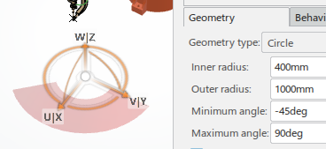
In the Geometry tab, select the Geometry
type to specify the shape of the plane for the sensor.

Each available Geometry type provides a set of parameters specific to that type.
- Circle
-
- Inner radius
- Outer radius
- Minimum angle
- Maximum angle
-
- Triangle
-
- Height
- Width
-
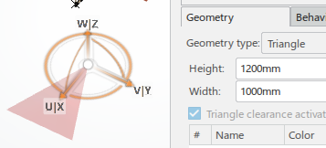
- Rectangle
-
- Length
- Width
-
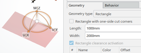
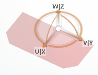
- When selected, Rectangle with one-side cut corners provides
a rectangle with the corners cut on the side opposite the origin.
-
Click
 to create a
clearance specification for the sensor.
Each clearance defined specifies an area of the plane that will produce a specific output signal for the defined area. You can define multiple clearances and specify the color of each by clicking the respective Color swatch.
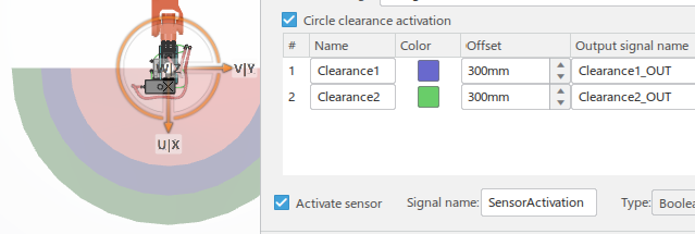
In the above example, Circle clearance activation activates the output signals for any defined clearances.
-
In the Behavior tab, Simulation frequency
specifies the rate at which the sensor will perform detection, independently of the
simulation step size.

Options provided in the Behavior tab allow you to define filters that control when output signals are required to be emitted, depending on the sense objects. You can also define advanced output signals, where detected attributes can be output as a specific signal.
-
In the Filter section:

Select Filtering moving object only to detect only those objects that move during the simulation. This guards against detecting any fixed objects that may be in the detection zone when the simulation starts.
Select Filtering specific objects from their attributes to activate any filters that have been defined.
-
Click
 to create a new
filter that is based on attributes.
The Filter on attribute dialog box appears.
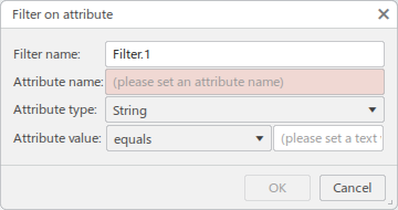
Provide an Attribute name and select and Attribute type.
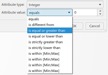
Select a condition from the Attribute value list, and enter a value that the condition is validated against. The contents of the the Attribute value list are dependent on the Attribute type selected.
-
Click OK to create the filter and return to the
Creation of plane sensor dialog box.
The new filter appears in the Filter list.

-
In the Output signal(s) section:

-
Click
 to create a new
output signal.
The Output on attribute dialog box appears.
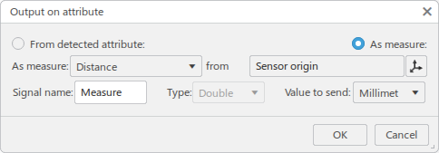
By default, As measure is selected as the type of output signal to create, and the dialog box is configured to create a signal based on Distance or Angle.
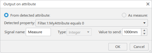
Select From detected attribute to select an an attribute from the Detected property list.
-
Click OK to create the output signal.
The output signal appears in the Output signal(s) list.

-
In the Creation of plane sensor dialog box, click
OK to create the plane sensor.
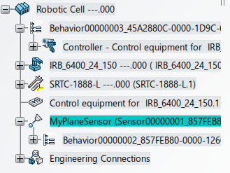
The new sensor appears in the tree.
