Activating and Using the Toolpath-Mesh Intersection Module

The toolpath-mesh intersection module enables simulations of a wide range of additive manufacturing processes. The functionality provides a high level of user control and customization using the Toolpath-Mesh Intersection Utility Routines, user subroutines, and table collections (see Table Collections, Parameter Tables, and Property Tables).

This page discusses:

This section describes a general workflow for the simulation of an additive manufacturing process using user subroutines and utility routines. The toolpath-mesh intersection module is also used in special-purpose techniques for common additive manufacturing processes. You do not have to invoke the toolpath-mesh intersection module utilities or the user subroutines to use the special-purpose techniques.

Supported Elements

Linear and quadratic 4-, 5-, 6-, 8-, 10-, 15-, and 20-node solid elements and 3-, 4-, 6-, and 8-node shell elements with constant shell thickness are supported. For shell elements, the middle surface of the shell must be the reference surface.
Simulating Controlled Deposition of Raw Materials

You can use progressive element activation in a structural or a thermal analysis to simulate controlled deposition of raw materials. You can define a specific type of toolpath (for example, the infinite line or the box toolpath) that best approximates the sequence of the material deposition for the additive manufacturing process and compute the intersection of that toolpath with the finite element mesh. You can use the geometric information of the intersection to define the active/inactive status of elements at a given increment by invoking the toolpath-mesh intersection module utilities from the user subroutines that are associated with the progressive element activation.

Table 1. User subroutines associated with the progressive element activation.
UEPActivationSetup

Set up data needed for the toolpath-mesh intersection module for material deposition and the evolving free surface.

UEPActivationVol

Find the intersection information from the toolpath-mesh intersection module and define active/inactive status of elements and/or volume fraction of the element based on the intersection information.

Specify the volume fraction increase for element activation.

Optionally, specify material orientation and eigenstrain components to be applied upon activation.

UEPActivationFacet

Specify the facet area fraction of an element to apply a film or radiation condition during progressive element activation.

Simulating Laser-Induced Heating

You can define a moving heat flux to simulate laser-induced heating in a thermal analysis. You can define a specific type of toolpath that best approximates the motion and the nature of the heat source for the additive manufacturing process. You can use the geometric information of the intersection to define a heat flux in an element at a given increment by invoking the toolpath-mesh intersection module utilities from the user subroutines that are associated with the moving heat flux.

Table 2. User subroutines associated with the moving heat flux.
UMDFluxSetup

Set up data needed for the toolpath-mesh intersection module for the moving heat source.

UMDFlux

Prescribe the heat flux from the moving heat source.

Additive Manufacturing Process Simulation Workflow

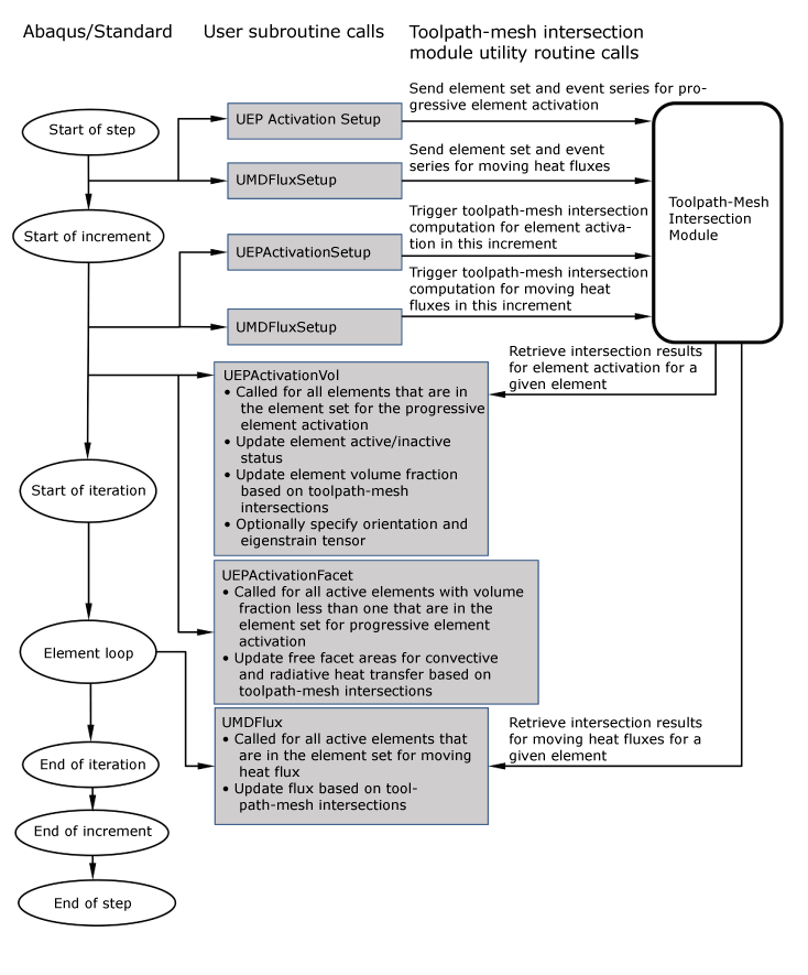
The flowchart in Figure 1 depicts a workflow of a typical additive manufacturing process simulation.

The workflow of a typical AM process simulation.