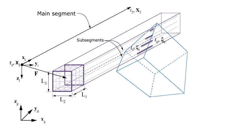
Using the Subsegment Approach
Figure 1 depicts intersections of a box toolpath with a finite element, , using the subsegment approach. The toolpath is defined by a box attached to a reference point that is moving along the path connecting points such that the reference point is at at time . A segment-specific local coordinate system is defined by the vectors , , and . Vector is along the segment connecting two successive points, and is a user-defined vector. The origin of this local system is at the start point of the segment. The box is oriented along the local coordinate system directions, and the center is at a constant user-defined offset, , from the reference point on the segment. The box lengths , , and along the local directions are user defined. The box is divided into a user-defined number of smaller boxes. It is assumed that a subsegment starts at the center of each smaller box and is parallel to the main segment. A user-defined weight is associated with each subsegment. The weight is multiplied with the field associated with the main segment to obtain a field associated with the subsegment. The sum of the weights of all of the subsegments is usually equal to one. For a given element, the toolpath-mesh intersection module computes the number of intersections of subsegments with the element, the coordinates of the start and end points (s and e, respectively, expressed in the element reference coordinate system), and the start and end times (ts and te, respectively) for each intersection.