A toolpath represents the motion of a given component of a machine
tool such as a laser source, a recoater roller, or a wire-feed nozzle. A
toolpath is defined by a geometric shape attached to a reference point that
moves along a path.
The path is defined by connecting a collection of points in
space and time. An event series defines the collection of points. The first
field defined in the event series describes a state of the tool, such as the
laser power, the "on/off" state for a recoater roller, or a wire-feed nozzle.
This field is assumed to be constant between two consecutive points. A
zero-valued field indicates the "off" state of the tool.
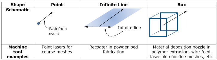
Three shapes are considered for toolpath-mesh intersection: a point, an
infinite line, and a box (see
Figure 1).
These shapes provide different levels of abstraction to characterize the shape
of the tool depending on the particular application. In addition to these three
shapes, a scan pattern that describes the idealized motion of a tool instead of
the actual path of the motion can be used. The topics that follow list some of
the quantities computed by the toolpath-mesh intersection module for each shape
and a scan pattern. For a complete list of the quantities computed by the
module, see the tables in
Data Retrieval Utility Routines.
Point, infinite line, and box toolpaths.