The fluid exchange capability is very general and can be used to define flow
in and out of a cavity either as a prescribed function or based on the pressure
difference arising from analysis conditions. The flow behavior in
Abaqus/Standard
is based on mass fluid flow, and the behavior in
Abaqus/Explicit
can be based on mass fluid flow or heat energy flow. You must associate the
fluid exchange definition with a name.
Flow between a Single Cavity and Its Environment
To define flow between a fluid cavity and its environment in
Abaqus/Explicit,
specify the single reference node associated with the fluid cavity. In the
discussion that follows this fluid cavity is referred to as the primary cavity.
When the flow is defined as a prescribed function, the flow can either be into
or out of the primary cavity. If the flow is into the cavity, the properties of
the material flowing in are assumed to be the instantaneous properties of the
material in the cavity itself. When the flow behavior is based on analysis
conditions, the mass flow can occur only out of the primary cavity but the heat
energy flow can be either into or out of the primary cavity. For the case of
mass flow
Abaqus
will use the fluid cavity pressure and the specified constant ambient pressure
to calculate the pressure difference used to determine the mass flow rate. For
the case of heat energy flow
Abaqus/Explicit
will use the fluid cavity temperature and the specified constant ambient
temperature to calculate the temperature difference used to determine the heat
energy flow rate.
Flow between Two Fluid Cavities
To define flow between two fluid cavities, specify the reference nodes
associated with the primary and secondary fluid cavities. When the flow is
based on analysis conditions, the fluid will flow from the high pressure or
upstream cavity to the low pressure or downstream cavity and the heat energy
will flow from the high temperature to the low temperature.
Specifying the Effective Area in an Abaqus/Explicit Analysis
The flow rate from the primary cavity for any fluid exchange property is
proportional to the effective leakage area. The leakage area may represent the
size of an exhaust orifice, the area of a porous fabric enclosing the cavity,
or the size of a pipe between cavities.
In an
Abaqus/Explicit
analysis you can specify the value of the effective leakage area directly.
Alternatively, you can define a surface that represents the leakage area by
specifying the name of the surface on the boundary enclosing the primary fluid
cavity. The effective area for fluid exchange is based on the area of the
surface unless you specify the area directly or define the effective area with
user subroutine
VUFLUIDEXCHEFFAREA. If both the effective area and a surface are specified,
the area of the surface is used only to determine blockage; see
Accounting for Blockage due to Contacting Boundary Surfaces
below. If neither area is specified, the effective area defaults to 1.0.
You can also define the effective leakage area with user subroutine
VUFLUIDEXCHEFFAREA (see
VUFLUIDEXCHEFFAREA)
if leakage needs to be modeled as a function of the material state in the
underlying elements of the specified surface. For example, this subroutine can
be used to define the leakage area at an element level for modeling fabric
permeability in uncoated airbags where the leakage can vary locally depending
on the strains in the yarn directions and the angle between the fabric yarns.
Only membrane elements are supported for use with
VUFLUIDEXCHEFFAREA.
Fluid Exchange through Ruptured Surfaces
Elements enclosing fluid cavities may fail and create a ruptured leakage area allowing
for fluid exchange. For example, two fluid cavities that share a common wall modeled by
membrane elements will not exchange fluid as long as the membrane elements remain intact.
When any of the shared membrane elements fail, fluid will be exchanged through an
effective area determined by the sum of the area of the failed elements. In essence, the
failed elements become holes in the membrane through which fluid can flow.
In an Abaqus/Explicit analysis you can define a surface set whose underlying elements may fail and allow
fluid and/or heat energy to be exchanged through the surfaces of the failed elements. The
effective area for the fluid exchange is computed from the surfaces of the failed
elements.
For a high pressure fluid chamber, such as a balloon, rupture of a small portion of the
enclosing surface can completely destroy the fluid chamber. In this case you can choose to
deactivate the fluid cavity by setting a maximum rupture area ratio. The area ratio is
defined as the area of the surfaces from the failed elements over the total area of the
user-defined surface set for the fluid exchange. Once the current rupture area ratio
exceeds the specified maximum, the cavity pressure is no longer applied to the fluid
cavity surfaces.
In a fluid cavity computation only the failure of the elements used to define the fluid
cavity can be detected. If a fluid cavity is physically enclosed by multiple layers of
elements, the failure of the immediately adjacent elements creates a leakage path for
fluid exchange even though no physical path exists. In such cases, fluid exchange based on
the surfaces of failed elements should be used with caution.
Application of Fluid Cavity Pressure on a Fluid Exchange Surface
You can control how the effect of the cavity pressure on a fluid exchange
surface is accounted for in
Abaqus/Explicit.
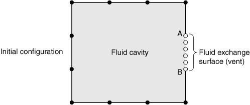
By default, the cavity pressure generates forces at all of the fluid exchange
surface nodes, using the same method as for other portions of the fluid cavity.
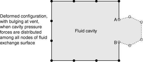
Optionally, the resultant force of the cavity pressure on the fluid exchange
surface can be distributed among only the nodes that lie on the perimeter of
the fluid exchange surface (for example, of the nodes shown on the fluid
exchange surface in
Figure 1,
only the nodes at locations A and B lie on the perimeter). This option can be
used to avoid local bulging of a vent surface that will cause inaccurate
computation of the leakage area.
Figure 2
shows an example of bulging when cavity pressure forces are distributed among
all nodes of a vent surface.
In an Abaqus/Explicit analysis, when elements enclosing a fluid cavity fail, the fluid cavity pressure is not
applied on the surfaces of those failed elements, which may help prevent potential
numerical issues associated with free-flying nodes of failed elements enclosing the fluid
cavity.
Initial configuration of a fluid exchange surface. Deformed configuration of a fluid exchange surface.
Defining the Fluid Exchange Property
There are several different types of fluid exchange properties available in
Abaqus
to define the rate flow from a fluid cavity to the environment or between two
cavities. The fluid exchange property can be as simple as prescribing the mass
or volume flow rate directly. More complex leakage mechanisms such as those
found on automotive airbags can be modeled by defining the mass or volume
leakage rate as a function of the pressure difference,
;
the absolute pressure, ;
and the temperature, .
The heat loss due to heat transfer through the surface of the cavity can be
modeled in
Abaqus/Explicit
by prescribing the heat energy flow rate directly or by defining the heat
energy flow rate as a function of the temperature difference,
;
the absolute pressure, ;
and the temperature, .
Alternatively, in
Abaqus/Explicit
the mass flow rate and/or heat energy flow rate can be specified in user
subroutine
VUFLUIDEXCH.
For the purposes of evaluating the mass flow rate between two cavities, the
absolute pressure and temperature are taken from the high pressure or upstream
cavity. The mass flow is always in the direction from the high pressure cavity
to the low pressure or downstream cavity, and the heat energy flow is always in
the direction from the high temperature cavity to the low temperature cavity.
The cavity absolute pressure and temperature are always used to calculate the
flow between a cavity and the environment.
You must associate the fluid exchange property with a name. This name can
then be used to associate a certain property with a fluid exchange definition.
Specifying a Mass or Volume Flux
Fluid flux into or out of the primary fluid cavity can be defined directly
by prescribing the mass flow rate per unit area, .
The mass flow rate is
where A is the effective area.
Fluid flux can also be defined by prescribing a volumetric flow rate per
unit area, .
The mass flow rate is
where
is the density.
A negative value for
or
will generate flux into the primary fluid cavity. When a second fluid cavity is
not defined, the state of the fluid flowing into the primary cavity is assumed
to be that of the fluid already present in the primary cavity.
Specifying the Flow Rate Using the Viscous and Hydrodynamic Resistance Coefficients
The mass flow rate, ,
can be related to pressure difference by both viscous and hydrodynamic
resistance coefficients such as
where
is the pressure difference, A is the effective area,
is the viscous resistance coefficient, and
is the hydrodynamic resistance coefficient. The resistance coefficients can be
functions of the average absolute pressure, average temperature, and average of
any user-defined field variables. A positive value of
corresponds to flow out of the first cavity.
Specifying the Flow Rate through a Vent or Exhaust Orifice
The mass flow rate through a vent or exhaust orifice that can be
approximated by one-dimensional, quasi-steady, and isentropic flow is given
(Bird, Stewart and Lightfoot, 2002) by
where C is the dimensionless discharge coefficient,
A is the vent or exhaust orifice area,
is the temperature in the upstream fluid cavity,
is the absolute zero on the temperature scale being used, and
is the absolute pressure in the upstream fluid cavity. The pressure ratio,
q, is defined as
where
is the absolute pressure in the orifice. The critical pressure,
,
at which choked or sonic flow occurs is defined as
where
is the ratio of the constant pressure heat capacity, ,
and the constant volume heat capacity, :
The orifice pressure, ,
is then given by
where
is equal to the ambient pressure for flow out of a single fluid cavity or the
downstream cavity pressure for flow between two fluid cavities.
The value of the discharge coefficient can be a function of the absolute
upstream pressure, upstream temperature, and any user-defined field variables.
Fluid exchange through a vent or exhaust orifice is valid only for pneumatic
fluids and is available only in
Abaqus/Explicit.
Specifying the Flow Rate due to Fabric Leakage
The mass flow rate due to leakage through fabric can be expressed as
where C is the dimensionless fabric leakage or
discharge coefficient and A is the effective fabric
leakage area.
The value of the discharge coefficient can be a function of absolute
upstream pressure, upstream temperature, and any user-defined field variables.
Specifying a Table of Mass Flow Rate Versus Pressure Difference
The overall mass flow rate can be calculated from a specified mass flow rate
per unit area, ,
by
where A is the effective area.
In this case you can define the mass flow rate per unit area in a table
depending on the absolute value of pressure difference and, optionally, on the
average absolute pressure, average temperature, and average value of any
user-defined field variables. Values for
and must be positive
and start from zero.
Specifying a Table of Volumetric Flow Rate Versus Pressure Difference
The overall mass flow rate can be calculated from a specified volumetric
flow rate per unit area, ,
by
where A is the effective area and
is the density.
In this case you can define the volumetric flow rate per unit area in a
table depending on the absolute value of pressure difference and, optionally,
on the average absolute pressure, average temperature, and average value of any
user-defined field variables. Values for
and must be positive
and start from zero.
Specifying a Heat Energy Flux
In
Abaqus/Explicit
heat energy flux into or out of the primary fluid cavity can be defined
directly by prescribing the heat energy flow rate per unit area,
.
The heat energy flow rate is
where A is the effective area. A positive value for
generates heat flux out of the primary fluid cavity.
Specifying a Table of Heat Energy Flow Rate Versus Temperature Difference
The overall heat energy flow rate can be calculated from a specified heat
energy flow rate per unit area, ,
by
where A is the effective area.
In this case in
Abaqus/Explicit
you can define the heat energy flow rate per unit area in a table depending on
the absolute value of temperature difference and, optionally, on the average
absolute pressure, average temperature, and average value of any user-defined
field variables. Values for
and must be positive
and start from zero.
Specifying Mass Flow Rate and/or Heat Energy Flow Rate with a User Subroutine
The mass flow rate, ,
or the overall heat energy flow rate, ,
can be defined in
Abaqus/Explicit
using user subroutine
VUFLUIDEXCH (see
VUFLUIDEXCHEFFAREA).
Activating the Fluid Exchange Definition in Abaqus/Explicit
Fluid exchange will not occur in
Abaqus/Explicit
unless the fluid exchange definition is activated in an analysis step.
Varying the Magnitude of the Flow
By default, the magnitude of the flow is based on the specified flow
behavior. A time variation of flow magnitude during a step can be introduced by
an amplitude curve. The magnitude based on the specified flow behavior is
multiplied by the amplitude value to obtain the actual mass or heat energy flow
rate. For example, a time variation of prescribed mass or volumetric flux can
be defined.
An amplitude curve may be used to trigger an event for fluid exchange in the
middle of a step. For example, an airbag may deploy at some predetermined time
during a step, and it may be desirable to close off all exhaust orifices until
the actual deployment. A step amplitude curve that starts at zero and steps up
at deployment time could be used for this purpose.
Accounting for Blockage due to Contacting Boundary Surfaces
Abaqus/Explicit
can account for the blockage of flow out of a cavity due to an obstruction
caused by contacting surfaces. For example, flow out of an exhaust orifice may
be fully or partially blocked because it is covered by another contacting
surface.
Blockage can be considered for any fluid exchange property. However, a
surface must be defined on the boundary of the fluid cavity to be checked for
contact obstruction.
Abaqus/Explicit
will calculate the area fraction of the surface not blocked by contacting
surfaces and apply this fraction to the mass or energy flow rate out of the
cavity. You can control the combination of surfaces that can cause blockage.
Abaqus/Explicit
will not consider contacting surfaces to cause blockage unless you specify that
they can potentially cause blockage (see
Contact Blockage).
Limiting the Flow Direction
By default, flow can occur both in and out of the primary fluid cavity when
a second node is included in the fluid exchange definition. In addition, heat
energy flow can occur in both directions when flow is defined between a single
cavity and its environment. You can limit the flow direction in
Abaqus/Explicit
in these cases such that fluid or heat energy flows only out of the primary
fluid cavity. This method is relevant only for a fluid exchange definition
based on analysis conditions and not on prescribed mass, volume, or heat energy
flux.
Activating the Fluid Exchange Based on the Change in the Leakage Area
The flow between cavities can be activated in
Abaqus/Explicit
based on a change in the area of the surface defining the effective area. You
need to specify the ratio of the actual surface area to the initial effective
area, which represents the threshold value for triggering the fluid exchange.
The effective area used for the fluid exchange between the cavities (or between
the cavity and the ambient) is the area difference between the actual area and
the initial area.
Activation in Multiple Steps
By default, when you modify the activation of a fluid exchange definition or
activate a new fluid exchange definition, all existing fluid exchange
activations in the step remain. When modifying an existing activation, all
applicable data must be respecified.
Activated fluid exchange definitions remain active in subsequent steps
unless deactivated. You can choose to deactivate all fluid exchange definitions
in the model and optionally reactivate new ones. If you deactivate any fluid
exchange definition in a step, all fluid exchange definitions must be
respecified.
Specifying Mass Flux in Abaqus/Standard
In
Abaqus/Standard
the amount of fluid in a cavity can be varied in a step. An amplitude curve can
be used to define the mass flow rate during the particular step.
References
Bird, R.B., W. E. Stewart, and E. N. Lightfoot, Transport
Phenomena, Wiley, New
York, 2002.