The lumped kinetic molecular method (LKM)
is a particle method that approximates the macroscopic behavior of a gas. It is
based on the kinetic theory of gases that assumes that all gases are composed
of an enormous number of extremely small molecules in a constant state of
random motion. For example, only four grams of helium contain
molecules with a Van der Waals radius of
m. The presence of such a large number of molecules allows for the motion of
the gas molecules to be treated in a statistical manner. The average behavior
of the molecules determines the macroscopic gas behavior. Because numerical
modeling of every gas molecule is impractical, the
LKM method reduces the size of the problem by
lumping many gas molecules into a single gas particle (preserving the
macroscopic gas behavior). In the LKM method
we solve for the motion of gas particles.
According to the kinetic theory of gases, the Maxwell-Boltzmann distribution
describes the speed of the gas molecules at a given temperature.
Figure 1
shows the Maxwell-Boltzmann speed distribution for helium atoms at a
temperature of 300 Kelvin. The molecules of gas collide elastically with each
other, as well as with the walls of the container. The pressure on the
container wall is the result of collisions with the wall. The root mean square
(RMS) velocity of the gas particles is given by ,
where m is the mass of the gas molecule, and
T is the absolute temperature of the gas. This link between speed
and temperature allows the solution of the gas flow problem in terms of its
molecular velocities as a fundamental problem variable.
Maxwell-Boltzmann speed function.
The LKM method is based on the following assumptions:
Lumped particles are rigid spherical particles that collide elastically.
Lumped particles obey the Maxwell-Boltzmann speed distribution.
Lumped particles modeling a monatomic gas have only translational
energy.
Lumped particles modeling a polyatomic gas have both translational and
rotational energy.
The temperature of the gas is low enough to ignore vibrational energy.
No attractive or repulsive forces exist between particles.
The pressure exerted by the gas on a structure is the combined result of
particle collisions over time on the surface.
The accuracy of the prediction of the LKM
method depends on the size and the number of lumped molecules. Using too few
particles or using particles that are too large can lead to inaccurate
solutions. While a large number of particles in general increases the accuracy
of the solution, it also increases the computational cost. The optimal number
of particles that gives an accurate solution at an acceptable computational
cost depends on the amount of gas, the cavity size, and the discretization of
the cavity surface mesh. For a small-sized problem, 100,000 gas particles may
be sufficient, while for a larger problem, 400,000 gas particles may be
required. A general guideline is that the number of particles should be large
enough such that the ratio of the average facet mass to the gas particle mass
is above 30. This ratio is printed in the status (.sta)
file. You can use this ratio to check if the number of particles is sufficient
for the analysis.
Applications
The LKM method can be used to simulate the
deployment of airbags. Such types of analyses are commonly performed as part of
the occupant safety assessment of automobiles. Airbags are safety devices that
minimize injury to occupants during a vehicle crash. During a crash an airbag
undergoes rapid inflation followed by deflation, which cushions the impact
between an occupant and the interior of the vehicle. There are various types of
airbags, such as the driver airbag that is placed in the steering wheel, the
side curtain airbag that is placed in the door panel, and the side torso airbag
that is placed in the seat. Most airbags consist of a bag made out of a
flexible fabric, an inflator device, an electronic controller, and sensors.
Different types of inflators are used for the different types of airbags. Most
inflators consist of a cylindrical metal housing that contains the propellant
and an igniter. There are orifices in the housing of the inflator through which
hot gases escape when the inflator is fired.
The airbag can be tightly folded or wrapped around the inflator to fit the
assembly in a confined space such as the steering wheel. In the event of a
crash, the controller unit evaluates the signals from the sensors and fires the
igniter, setting off a controlled explosion in the inflator. The rapidly
expanding gases exit through the orifices in the inflator housing to deploy the
airbag. The deployment duration depends on the size and type of airbag and is
usually between 20-30 milliseconds. Finally, as the airbag gets squeezed
between the occupant and the vehicle, the gases escape through vents in the
airbag causing the airbag to deflate.
Figure 2
shows a sectional view of a partially deployed curtain airbag in contact with a
rigid hemispherical head form. A close-up view of a tiny volume of the gas in
the figure shows the randomly moving gas particles. In the simulation the
inflator introduces gas particles inside the airbag, imparting each particle a
random speed based on the Maxwell-Boltzmann speed function and a random
direction for its velocity. The impact of the fast moving gas particle against
the facets of the airbag results in the transfer of energy between the gas and
the airbag. The speed of a gas particle decreases as it collides with a facet
that is moving away from it, and the speed increases when the gas particle
collides with a facet that is moving towards it. All collisions are elastic.
The inflator continues to introduce more gas particles into the airbag, pushing
it open. As the speed of more gas particles decrease after collision with the
expanding airbag, the root mean square (RMS) velocity of the gas particles
decreases. This decrease in the average velocity of the lumped molecules is
equivalent to the cooling of the injected gas.
Partially deployed airbag.
Model Set-Up
A fluid cavity must be associated with the airbag interior surface. The
fluid cavity is used only to calculate a cavity volume. The cavity volume is
used to compute the output average pressure in the cavity. The fluid cavity
does not contribute any pressure loading. The pressure loading is due only to
particle impacts.
For the LKM method, you must specify the
universal gas constant and the Ludwig Boltzmann constant.
Defining an Inflator
An inflator is a device that injects gas into an airbag during deployment.
The particle generator works as an inflator for the
LKM method. During the analysis, the particle
generator injects gas particles at specific locations inside the airbag. The
particle generator must be associated with the gas behavior and with the mass
flow rate and the temperature history of the inflator to determine the number
of particles to add per time increment and their velocities. The fluid cavity
associated with the airbag must also be associated with the particle generator.
See
Particle Generator for
further details.
LKM particles of a given gas species have
the same size. The size is determined automatically from the estimated maximum
airbag volume and the ratio of the assumed mean free path to the size of the
lumped molecule. The actual mean free path is the average distance lumped
particles travel between collisions, and it is an unknown quantity. You must
specify the maximum airbag volume in the particle generator definition. A
reasonable estimate of the maximum airbag volume results in a good balance
between accuracy and performance.
The ratio of the assumed mean free path to the size of a lumped molecule is
used only for determining the size of the gas particles. The default value of
this ratio is 500. The default value works well for most airbag models. To
reduce the automatically calculated particle size, you can increase the value
of this ratio. The actual ratio of the mean free path to the particle size is
an outcome of the solution and depends on the particle concentration during the
analysis.
Defining Inflator Geometry
Inflators come in different shapes and sizes depending on the airbag in
which they are used. Typically, the gas is injected through orifices that are
located around the inflator housing.
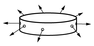
Figure 3
shows a schematic diagram of a side-firing inflator device with orifices
arranged around the side of the inflator housing. The particle generator that
works as the inflator in the LKM method only
requires the location and orientation of the orifices of the inflator. A single
planar facet can be used to approximate an orifice.
Figure 4
shows the inlet facets of the corresponding particle generator model. The
center of each facet coincides with each of the corresponding nine inflator
orifice centers. The outward normal shown on each of the facets indicates the
direction in which the gas particles are generated. Gas particles are generated
in random directions in the front half plane of each facet of the inlet
surface. The facets together form the inlet surface of the particle generator.
It is recommended that you use surface elements to define the inlet facets. The
particle generator uses the inlet facets merely as geometrical entities through
which particles are injected into the problem domain. The gas particles do not
have any contact interaction with the inlet facet. Therefore, it is important
that you ensure that contact is not defined between the inlet surface and the
gas particles.
Inflator. Inflator modeled with particle generator.
The inlet facet should be many times larger than the actual particle
diameter. This ensures that the particle generator is able to inject a large
number of particles without blocking the inlet facets. The approximation of the
orifice geometry and size with a single planar facet does not have a
significant influence on the accuracy of the solution. The location of the
inlet facets inside the airbag, the facet arrangement, and the facet
orientation are important to capture where and how the gas is injected into the
airbag. The inlet facets should be rigidly attached to the structure. This
ensures that the inlet facets maintain their shape and size and undergo rigid
body motion as the structure deforms and moves. You can use a
BEAM MPC type to rigidly connect the nodes of
the inlet facet to the structure.
For further details on defining inlet geometry and inlet blocking behavior
of a particle generator, see
Particle Generator.
Defining Inflator Mass Flow Rate and Temperature Data
The mass flow rate and temperature data are used to generate lumped
molecules for a gas species. The mass flow rate and temperature of a gas
species can be specified in tabular form. This form of specifying the mass flow
rate and temperature for the inflator is identical to the uniform pressure
method (see
Inflator Definition).
The fluid inflator properties must be associated with a particle generator.
The particle generator uses the mass flow rate to determine the incremental
amount of gas that must be generated at any given time. The particle generator
ensures that an equivalent number of particles are generated. The mass of a gas
particle depends on the total amount of gas and the maximum number of particles
requested. For further details on how the particle generator accounts for the
incremental mass that must be generated, see
Particle Generator.
Triggering the Inflator
There is usually a time lag between the start of the analysis and the
deployment of the airbag in a crash simulation. In the
LKM method this time delay is introduced
through an amplitude curve. The common form of such a curve is the step
function. The area under the amplitude curve is the value of the time the
particle generator uses to look up the fluid inflator property data to compute
the mass flow rate and the temperature of each gas species. The particle
generator begins firing when the step-function curve becomes nonzero. You can
use a constant unit amplitude curve for zero time delay.
Elements
The LKM method uses PD3D elements to model the lumped gas molecules. The actual elements
are generated automatically during the analysis and appended to the element set
associated with the discrete section. The properties of the specific gas
species are associated with the elements by referring to the fluid behavior
from the discrete section.
Abaqus/Explicit
computes the size and mass of lumped molecules automatically. The density
specified on the discrete section definition is ignored in the
LKM method. The mass and rotary inertia
proportional damping value on the discrete section definition are also ignored.
Usually, gas particles are contained, but sometimes a few particles can
escape and cause numerical problems. To deactivate contact between particles
that leak out of the airbag with the surrounding structures, you can specify
the coordinates of the lower left corner and upper right corner of a control
box. You should ensure that the control box is large enough to accommodate the
fully deployed airbag including any motion of the airbag. All collisions of
particles outside the control box are ignored. You can specify the name of the
section control on the discrete section to associate the control box with the
airbag.
Switching from Lumped Kinetic Molecular Method to Uniform Pressure Method
During the early phase of deployment, the pressure inside the airbag is
nonuniform. The LKM method can capture such
nonuniformity of pressure inside the airbag. During the early phases of
deployment, it is recommended that you use the
LKM method. As the bag approaches full
deployment, the pressure inside the airbag tends toward a uniform value. The
uniform pressure method (UPM) is
computationally efficient for such situations. Therefore, for computational
efficiency, switching from LKM to
UPM when the airbag has nearly deployed is
desirable. You can specify the time when
Abaqus/Explicit
switches from LKM to
UPM. At the point of switching, the particles
are deactivated and their motion is frozen. You should exercise caution when
specifying the switching time. Switching too early when the pressure in the
airbag is nonuniform can result in an inaccurate solution, while switching too
late sacrifices computational efficiency. Another important reason to switch
from LKM to
UPM is to account for leakage of gas via vents
and fabric of the airbag. You can activate the exchange of fluid between the
airbag and its environment at the same time as the switching occurs. For more
information, see
Fluid Exchange Definition.
Interactions
In the LKM method particles collide
elastically with each other, as well as with the surrounding structure. All
collisions preserve the momentum, as well as the energy of the particles.
Because contact interactions form the basis for the
LKM method, the general contact definition for
LKM is very similar to the general contact
definition for a discrete element method model. Each
LKM particle is typically involved in the
following contact interactions:
Contact with another particle
from the same gas species.
Contact with a structural facet.
Separate element-based surfaces spanning particles of each gas species must
be used to list each of the above contact interactions. A surface interaction
must be defined for each of the contact interactions involving the particles. A
special pressure-overclosure type is required to ensure purely elastic
collisions. Dissipative contact interactions such as friction and contact
damping are ignored for the LKM method.
Abaqus/Explicit
adjusts the time increment automatically to ensure that lumped molecules are
tracked accurately.
Output
The local pressure at any instant of time on a patch of elements is the sum
of the particle impact forces divided by the area of the patch. Due to the
discrete nature of the impacts, the local pressure is noisy. Therefore,
filtering is recommended for any local pressure computation. In the
LKM method the mass, average temperature, and
average pressure of a gas species are of interest. Three integrated output
variables (PDMASS, PDTEMP, and PDPAVG) can be
used to request history output for mass, average temperature, and average
pressure for a specific gas species.
Limitations
The following limitations apply:
Only the particle generator can inject gas in the fluid cavity in the
LKM method. Therefore, the initial gas cannot
be modeled in the LKM method. To approximate
the initial gas, the particle generator can be fired for a short duration and
then halted at the start of the analysis before the main analysis.
The
LKM method cannot be used in conjunction with
other particle methods, such as SPH or
DEM.
An
LKM analysis with more than one interacting
gas species is not supported.
Input File Template
PHYSICAL CONSTANTS, UNIVERSAL GAS CONSTANT=R, BOLTZMANN=K
...
FLUID CAVITY, REF NODE=flucavrefnode, SURFACE=airbag_surface, ADIABATIC,
BEHAVIOR=air_gas, AMBIENT PRESSURE=value of ambient pressure
...
DISCRETE SECTION, ELSET=air_particles, FLUID BEHAVIOR=air_gas, CONTROLS=lkm ccontrol
blank data lineSECTION CONTROLS, NAME=lkm control
blank data lineblank data linecxl, cyl, czl, cux, cuy, cuz, 1
FLUID BEHAVIOR, NAME=air_gas
MOLECULAR WEIGHTvalue of molecular weightCAPACITY, TYPE=polynomialvalue of heat capacity coefficients separated by commas
...
PARTICLE GENERATOR, NAME=inflator, MAXIMUM NUMBER OF PARTICLES=number of particles,
FLUID CAVITY REFNODE=flucavrefnode, CAVITY VOLUME=final volume of airbagPARTICLE GENERATOR INLET, SURFACE=name of inlet surface
...
PARTICLE GENERATOR MIXTURE
air_particles
...
FLUID INFLATOR PROPERTY, NAME=inflator prop, TYPE=TEMPERATURE AND MASS
time0, temp0, M0
time1, temp1, M1
...
FLUID INFLATOR MIXTURE, NUMBER SPECIES=1, TYPE=MASS FRACTION
air
time0, 1.0
time1, 1.0
...
SURFACE, NAME=gas_surf
SURFACE, NAME=wall_surf
SURFACE INTERACTION, NAME=lkm_inter
SURFACE BEHAVIOR, PRESSURE-OVERCLOSURE=LKM
...
STEPDYNAMIC, EXPLICIT, ELEMENT BY ELEMENT
, total timePARTICLE GENERATOR FLOW, FLUID INFLATOR PROPERTY=inflator prop,
GENERATION TIME AMPLITUDE=gen time amp, FLOW AMPLITUDE=flow amp, MASS FLOW RATE TYPE=TOTAL
...
CONTACTCONTACT INCLUSIONS
gas_surf, gas_surf
gas_surf, wall_surf
CONTACT PROPERTY ASSIGNMENT
gas_surf, gas_surf, lkm_inter
gas_surf, wall_surf, lkm_inter