allow for the description of a beam cross-section including multiple
materials and complex geometry;
are meshed in Abaqus/Standard with two-dimensional warping elements, which have an out-of-plane warping displacement
as the only degree of freedom for 1-DOF warping elements and two in-plane and one
out-of-plane warping displacements as degrees of freedom for 3-DOF warping elements;
generate beam cross-section properties that can be used in a
subsequent beam element analysis in either
Abaqus/Standard
or
Abaqus/Explicit;
allow only isotropic linear elastic material behavior or orthotropic linear elastic
material behavior for 1-DOF warping elements;
allow isotropic linear elastic material behavior, fully three-dimensional orthotropic
linear elastic material behavior, and fully anisotropic linear elastic material behavior
for modeling composite beam cross-sections with 3-DOF warping elements; and
allow stress and strain postprocessing on the beam element model or
the two-dimensional warping element model.
The response of some structures is beam-like, yet the beam cross-section geometry or
multimaterial makeup of the cross-section do not permit the use of a predefined library beam
cross-section. In these cases a meshed cross-section can be used to model the beam
cross-section and to generate beam cross-section properties appropriate for subsequent use
in a Timoshenko beam analysis. The beam properties are generated assuming a thick-walled
(solid) cross-section with unconstrained out-of-plane and, optionally, in-plane warping.
Therefore, open-section beam elements cannot use the beam cross-section properties generated
from the meshed section (see About Beam Modeling). The generated
beam cross-section properties include axial, bending, torsional, and transverse shear
stiffnesses; mass, rotary inertia, and damping properties; and the centroid and shear center
of the cross-section. In addition, the equivalent beam cross-section properties include
information on stress recovery, such as the warping functions and their derivatives.
A typical example of a structure that requires a meshed cross-section is the hull of a ship
for whipping analysis, where the ship's hull has a multi-cell and multimaterial
construction. Other examples include an airfoil-shaped rotor blade or wing and a layered
composite I-beam (with fibers running along the length of the beam axis or perpendicular to
it).
Modeling Approach
As shown in Figure 1, a meshed cross-section allows for a complex description of a beam cross-section: one
that can include an arbitrary shape, multiple materials, multiple cells, and nonstructural
mass. The basic idea is to create a two-dimensional finite element model of the beam
cross-section. The meshed cross-section is used in Abaqus/Standard to numerically calculate the properties required to characterize the structural response
of the cross-section in a subsequent beam element analysis. The two-dimensional Abaqus/Standard analysis writes the cross-sectional properties to an input-file-ready text file
(jobname.bsp). In the subsequent Abaqus/Standard or Abaqus/Explicit beam element analysis the beam elements requiring the meshed cross-section properties
include the text file jobname.bsp as the general beam section data.
Example of a meshed section profile.
In summary, the procedure for analyzing and postprocessing a beam analysis
using a meshed cross-section is as follows:
Mesh and analyze a two-dimensional
Abaqus/Standard
model of the beam cross-section.
Use the generated cross-sectional properties in an
Abaqus/Standard
or
Abaqus/Explicit
beam analysis.
Using the beam analysis results, postprocess from the beam model or the
two-dimensional cross-section model.
Meshing and Analyzing a Two-Dimensional Model of the Beam Cross-Section
The cross-section is meshed using special-purpose two-dimensional elements. There are two
classes of these warping elements (see Warping Element Library):
WARP2D3 (3-node triangular) and
WARP2D4 (4-node quadrilateral) elements
have one degree of freedom per node representing the out-of-plane warping
displacement.
WARPF2D3 (3-node triangular),
WARPF2D4 (4-node quadrilateral),
WARPF2D6 (6-node triangular), and
WARPF2D8 (8-node quadrilateral) elements
have two additional degrees of freedom per node representing the in-plane warping
displacements.
The warping elements use a solid section definition; no section data are required.
Adjacent elements in the cross-sectional mesh must share common nodes; mesh refinement
using multi-point constraints is not allowed. The mesh can contain either 1-DOF warping
elements or 3-DOF warping elements; you cannot mix the two element classes in the same
analysis.
Each element in the cross-sectional mesh can refer to a different elastic material. For
1-DOF warping elements, you can use either isotropic (see Defining Isotropic Elasticity) or
orthotropic linear elastic material behavior (see Defining Orthotropic Elasticity for 1-DOF Warping Elements).
Alternatively, you can specify density (Density) as the only
material property, which is useful for modeling nonstructural masses (such as fuel in a
tank). For 3-DOF warping elements, the following material behaviors are supported:
3-DOF warping elements are particularly useful if you want to model composite beam
cross-sections (such as wind turbine rotor blades).
The model is then analyzed by using the beam section property generation procedure within
the step definition. This cross-section analysis numerically calculates the geometric,
stiffness, and inertial properties of the section, including the warping function and
shear center (see Meshed beam cross-sections) and writes
the calculated properties to the jobname.bsp text file. The contents
of this text file, which can be used in a subsequent Abaqus/Standard or Abaqus/Explicit beam analysis, are described in detail below.
Defining the Origin of the Cross-Section
By default, the origin of the cross-section is the origin of the
coordinate system used to define the mesh. You can override this default and
input the coordinates of the origin directly or specify that the origin
coincides with the shear center or centroid of the cross-section. A nondefault
origin is particularly useful when the beam node to be used in the actual
analysis does not coincide with the origin of the two-dimensional coordinate
system.
Defining the Tangent Direction of the Beam Element Centerline for 3-DOF Warping Elements
The beam centerline is the curve that connects the corner nodes of the beam elements to
which you assign the properties that you compute with the beam section property
generation procedure. By default, Abaqus assumes that the beam centerline tangent direction is parallel to the cross-section
normal direction. For 3-DOF warping elements, you can override this default and specify
the direction cosines of the beam centerline tangent. Thereby, if the beam centerline
tangent is inclined with respect to the cross-section normal direction, you can take
into account the effect of this inclination for the beam element cross-section properties.
Defining the Curvatures and the Torsion of the Beam Element Centerline for 3-DOF Warping Elements
By default, Abaqus assumes that the beam centerline is straight and that beam element cross-sections
have the same orientation in space. If this is not the case, 3-DOF warping elements can
take into account the influence of the curvatures and torsion of the beam centerline on
the stiffness properties of the associated beam element cross-sections. For example, you
can model a rotor blade that is prebent and pretwisted.
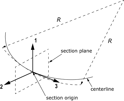
The beam centerline is the curve that connects the beam element nodes. When you
consider the projection of the beam centerline onto the plane that is normal to the
cross-section 1-direction (or 2-direction), the associated first (or second)
precurvature value is the reciprocal radius of the osculating circles. For example,
Figure 2 shows the osculating circle of the centerline projection onto the
plane that is normal to the 1-direction; the associated first precurvature is .
Precurvature.
The pretorsion is defined as the change in rotation of the beam elements’ cross-section
orientations about the beam centerline tangent with respect to the rotation-minimizing
frame along the centerline. For example, in Figure 3 the centerline is straight and the rotation-minimizing frames in the
cross-section planes are all parallel; the associated pretorsion for the depicted
cross-section orientations is .
Pretorsion.
Requesting Output at Particular Integration Points for 1-DOF Warping Elements
Output to the output database can be recovered during the actual analysis
at particular integration points on the cross-section. Requesting output at a
large number of cross-sectional points may degrade performance.
Contents of the Output Database
By default, the output database contains field output with warping displacements for
one frame for 1-DOF warping elements or for six frames for 3-DOF warping elements. For
1-DOF warping elements, the field output also contains section point strain and stress
recovery data for all element integration points. For 3-DOF warping elements, the strain
and stress recovery data is contained as strain and stress element output for the six
frames. The data in the first, second, and third frames represent the cross-section
warping fields for unit beam cross-section forces due to extension, shearing in the
1-axes, and shearing in the 2-axis of the cross-section, respectively. The data in the
fourth, fifth, and sixth frames represent the cross-section warping fields for unit beam
cross-section torques due to twisting, bending about the 1-axis, and bending about the
2-axis of the cross-section, respectively.
Contents of the jobname.bsp Text File
After the analysis to generate the cross-sectional properties completes, the
jobname.bsp text file contains the
following lines of data when you use 1-DOF warping elements:
The first two lines of data in the
jobname.bsp text file
correspond to the section property data for an arbitrarily shaped solid general
beam cross-section meshed with warping elements (see
Defining Linear Section Behavior for Meshed Cross-Sections).
If you requested output at particular integration points in the
two-dimensional cross-section model generation, the
jobname.bsp text file contains
the following additional lines:
SECTION POINTSsection point label, 2D element number, integration point numberE, , , , , , ,
...
where the set of two data lines is repeated for as many section points as
requested.
When you use 3-DOF warping elements, the
jobname.bsp text file contains the
following lines of data:
In this case, the cross-section properties might represent a fully coupled, linear
elastic behavior according to the 21 values of the symmetric 6 × 6 stiffness matrix. In
general, the elastic response to the different beam section strains, transverse shear,
axial stretch, bending, and torsion cannot be separated; and no unique centroid and
shear center locations can be defined. Depending on the material properties of the
two-dimensional cross-section mesh and the options that are defined for the analysis
procedure, some coupling terms might vanish, allowing for a transformation into the
representation of the cross-section properties that is used with 1-DOF warping elements.
Typically, this is the case only if the following conditions are met:
The beam element centerline has zero curvature and torsion.
The beam element centerline tangent direction is aligned with the cross-section
normal direction.
All elements have isotropic elasticity or orthotropic elasticity with one of the
elasticity tensor principal axes aligned with the cross-section normal
direction.
The corresponding properties are then printed into the
jobname.dat data file.
The cross-sectional property information written to the
jobname.bsp text file is read into
the general beam section definition in the subsequent beam analysis in Abaqus/Standard as described below.
Contents of the Flexible Body Interface File for 3-DOF Warping Elements
When you use 3-DOF warping elements, a flexible body interface
(.fbi) file is generated that contains
the cross-section mesh and its mass and stiffness properties,
recovery information for reconstructing the in-plane and out-of-plane warping
displacements, and
the associated strain and stress based on beam element cross-section forces and
torques.
The .fbi file uses a binary format, and you can assign the file to
Simpack Nonlinear SIMBEAM element cross-sections. Simpack expects .fbi file data in SI units. By default, Abaqus assumes that the cross-section mesh is defined in SI units. You can override the
default and specify the units used for the cross-section definition. The data are then
converted automatically to SI units before it is written to the
.fbi file.
Using the Generated Cross-Section Properties in a Beam Analysis
As discussed above, the section properties calculated and stored in the
jobname.bsp text file can be used in
an actual beam analysis to define cross-sections for beam elements. The data stored in the
jobname.bsp file correspond to the
section property data for an arbitrarily shaped solid general beam cross-section meshed
with warping elements (see Defining Linear Section Behavior for Meshed Cross-Sections).
Consequently, a simple method of inserting these data is to include the
jobname.bsp file in the beam analysis.
If the jobname.bsp file is generated using
3-DOF warping elements, you can only use the file in Abaqus/Standard. If the file is generated using 1-DOF warping elements, you can use the file in Abaqus/Standard and Abaqus/Explicit.
Postprocessing from the Beam Model or the Two-Dimensional Cross-Section Model
A tick mark contour plot can be used to visualize stress and strain output along the
length of the beam model. All stress and strain components requested for the
two-dimensional cross-section model generation are available. Contour plots of stress and
strain on the two-dimensional cross-section are also available. The section geometry is
read from the output database generated by the two-dimensional cross-section analysis,
while the generalized section results are read from the output database generated by the
beam analysis.
Initial Conditions
Initial conditions are not meaningful when generating beam section
properties and are ignored.
Boundary Conditions
Boundary conditions are not meaningful when generating beam section
properties and are ignored.
Loads
Loads are not meaningful when generating beam section properties and are
ignored.
Predefined Fields
Temperature and field variables are not allowed for meshed sections.
Material Options
Only the following material behaviors are allowed for meshed sections:
Warping elements must be used to mesh the two-dimensional cross-section. See
Warping Elements
for details.
Output
Element output is calculated during the actual beam analysis at the
integration points on the meshed cross-section that are selected in the
property generation analysis as described above. Output from the property
generation analysis is available only on the output database.
Input File Template
Generating the Cross-Section Properties in an Abaqus/Standard Analysis for Beams Having Isotropic or Orthotropic, Traction-Type Materials
Generating the Cross-Section Properties in an Abaqus/Standard Analysis for Composite Beams Having Fully Three-Dimensional Orthotropic or Fully Anisotropic Materials