Elements tested
- S3
- S3R
- S4
- S4R
- S4R5
- S8R
- S8R5
- S9R5
- STRI3
- STRI65
ProductsAbaqus/Standard Elements tested
Problem description
Model:There is an initial imperfection in both the cylindrical panel and the stiffener. Cylindrical panel: , where −9 9 and 0 200. Stiffener: , where 0 200 and 0 10. Material:Young's modulus = 2.1 × 10⁵, Poisson's ratio = 0.3, yield stress = 350. Boundary conditions:Tangential symmetry along edges 1 and 2 at = 9° (). Simply supported at end A for panel: (), for stiffener: (). Symmetry at for panel: (), for stiffener: (). Loading:Compressive, evenly distributed edge load. The RIKS algorithm is used to increment the load until the global z-displacement at point D exceeds 0.2. Reference solutionThis is a test recommended by the National Agency for Finite Element Methods and Standards (U.K.): Test 3DNLG-10 from NAFEMS Publication R0024 “A Review of Benchmark Problems for Geometric Non-linear Behaviour of 3D Beams and Shells (SUMMARY).” The published results of this problem were obtained with Abaqus. Thus, a comparison of Abaqus and NAFEMS results is not an independent verification of Abaqus. The NAFEMS study includes results from other sources for comparison that may provide a basis for verification of this problem. Results and discussionIn the following table, limit points 1 and 2 correspond to the peak and local minimum, respectively, of the load-displacement curve. To produce results comparable to those for S8R5/S9R5, the first-order elements require a finer mesh with half the nodal spacing in the curved direction of the panel. The limit loads for the thick shell element S8R are noticeably higher than others in this thin shell application, even when a fine mesh with the same nodal spacing as that used for the first-order elements is generated.
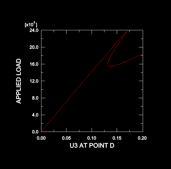
Response predicted by AbaqusSimilar load-displacement curves are obtained for all the test cases. The response predicted using S8R5 elements is shown below.  Input files
| ||||||||||||||||||||||||||||||||||||||||||||||||||||||||||||||