Elements tested
- CSS8
- S3
- S3R
- S4
- S4R
- S4R5
- S8R
- S8R5
- S9R5
- STRI3
- STRI65
- SC6R
- SC8R
ProductsAbaqus/Standard Elements tested
Problem description
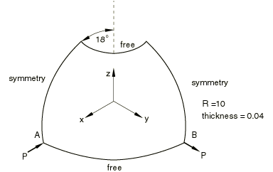
Material:Young's modulus = 6.825 × 10⁷, Poisson's ratio = 0.3. Boundary conditions:Symmetry on plane y = 0 (, symmetry on plane x = 0 (, at A to prevent rigid body motion. Loading:Inward and outward diametrical point loads (P = 100). Reference solutionThis is a test recommended by the National Agency for Finite Element Methods and Standards (U.K.): Test 3DNLG-9 from NAFEMS Publication R0024 “A Review of Benchmark Problems for Geometric Non-linear Behaviour of 3D Beams and Shells (SUMMARY).” The published results of this problem were obtained with Abaqus. Thus, a comparison of Abaqus and NAFEMS results is not an independent verification of Abaqus. The NAFEMS study includes results from other sources for comparison that may provide a basis for verification of this problem. Results and discussionThe following table shows the radial displacements at points A and B at three load levels. All the meshes have the same nodal spacing.
Response predicted by AbaqusSimilar load-displacement curves are obtained for all test cases. The response predicted using S4R elements is shown below. The curve for node A is for the negative displacement and load values.  Input files
| |||||||||||||||||||||||||||||||||||||||||||||||||||||||||||||||||||||||||||||||||||||||||||||||||||||||||