Shell elements subjected to uniform thermal loading

This examples illustrates the free thermal expansion of shell elements. The results are compared to the analytical solution.

This page discusses:

ProductsAbaqus/Standard

Problem description

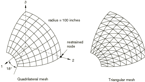
A one-eighth symmetrical segment of a spherical surface with a cutout is modeled as a shell section. Symmetry boundary conditions are applied appropriately to the section's edges. The structure has a thickness of 0.4 inch and a radius of 100.0 inches and is subjected to a uniform temperature change. The discretization of this surface yields the following meshes: one consisting of 64 quad elements for use with S4, S4R, S4R5, S8R, and SC8R elements and the other consisting of 128 triangular elements for use with STRI3, STRI65, S3/S3R, and SC6R elements. The shell section is heated uniformly from 0° F to 430° F.

The first step of each input file is a static linear perturbation step. In the second step the loading is repeated as a general step that accounts for geometric nonlinearities. Since the deformations are small, the displacements obtained in the second step are virtually the same as the displacements obtained in the linear perturbation step. In some of the input files, solution controls are used to relax the equilibrium tolerances somewhat. This is necessary because the nodal forces in the final solution are zero; hence, the maximum force and moment residuals are (almost) of the same order of magnitude as the force and moment norms.
Material properties

The material is isotropic with the following constants:

Young's modulus, E = 68.25 × 10⁶ psi
Poisson's ratio, ν = 0.3
Thermal expansion coefficient, α = 1.0 × 10⁻⁶ in/in°F

Analytical solution

The analytical solution to this problem is uniform radial expansion with zero stress.

Results and discussion

In establishing a reasonable numerical result for the shell section, acceptable stress output may be values that are at least five or six orders of magnitude smaller than those of a completely constrained shell section with identical geometry. If the modeled section were completely constrained, the temperature change would provide a uniform compressive stress calculated as σc=EαΔθ, where E=E/(1-ν) and Δθ is the temperature change. Using the material properties above and these relations, a fully constrained shell model should produce compressive stresses, σc, equal to 42,000 psi. Thus, an acceptable numerical solution would be less than approximately 0.1 psi.

All elements provide principal stresses that are well below this value for both the linear static analysis step (Step 1) and the geometrically nonlinear step (Step 2). In the linear static step all elements tested, with the exception of S4R5, provide maximum principal stress magnitudes that are O(10−8) psi or smaller. The S4R5 element's maximum principal stress magnitude is O(10−3) psi. The problem becomes more challenging when nonlinear geometry (NLGEOM) is included. In these tests this effect is reflected by the higher stress magnitudes of some of the geometrically nonlinear results of Step 2. Elements S3/S3R, STRI3, and S4R produce maximum principal stress magnitudes that are O(10−7) psi or smaller. Element S4 produces maximum principal stress magnitudes of O(10−6) psi. The principal stress magnitudes of STRI65, S4R5, and S8R elements—all O(10−2) psi—are considerable higher. However, even these relatively high stresses are considered to be very reasonable.

Figures

Figure 1. Meshes used in this analysis.