Kinematic Coupling Constraints

Kinematic coupling constraints limit the motion of a group of nodes to rigid body motion defined by a reference node.

In addition, kinematic coupling constraints:

  • can be applied only to specific user-specified degrees of freedom at the constrained nodes;

  • can be specified with respect to local coordinate systems at the constrained nodes; and

  • can be used in geometrically linear or nonlinear analysis.

The preferred method of providing a kinematic constraint of this type is described in Coupling Constraints.

This page discusses:

Typical Applications

The kinematic coupling constraints are useful in cases where a large number of nodes (the “coupling” nodes) are constrained to the rigid body motion of a single node and the degrees of freedom that participate in the constraint are selected individually in a local coordinate system. In many such cases MPCs either are not available or must be prescribed individually for each constrained node. A typical example is shown in Figure 1, where a kinematic coupling constraint is used to prescribe a twisting motion to a model without constraining radial motions. In other applications the kinematic coupling constraint can be used to provide coupling between continuum and structural elements.
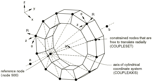
A kinematic coupling constraint used to transmit rotation to a structure while permitting radial motion.

Defining the Constraint

A kinematic coupling constraint requires the specification of a reference node, coupling nodes, and the constrained degrees of freedom at these nodes. The reference node has both translational and rotational degrees of freedom.

Kinematic constraints are imposed by eliminating degrees of freedom at the coupling nodes. Once any combination of displacement degrees of freedom at a coupling node is constrained, additional displacement constraints—such as MPCs, boundary conditions, or other kinematic coupling definitions—cannot be applied to any coupling node involved in a kinematic coupling constraint. The same limitation applies for rotational degrees of freedom.

Translational Degrees of Freedom

Translational degrees of freedom are constrained by eliminating the specified degrees of freedom at the coupling nodes. When all translational degrees of freedom are specified, the coupling nodes follow the rigid body motion of the reference node.

Rotational Degrees of Freedom

All combinations of selected rotational degrees of freedom result in rotational behavior that is identical to existing MPC types. Specifically:

  • Selection of three rotational degrees of freedom along with three displacement degrees of freedom is equivalent to MPC type BEAM.

  • Selection of two rotational degrees of freedom is equivalent to MPC type REVOLUTE.

  • Selection of one rotational degree of freedom is equivalent to MPC type UNIVERSAL.

Internal nodes are created by the kinematic coupling to enforce the constraints that are equivalent to MPC types REVOLUTE and UNIVERSAL. These nodes have the same degrees of freedom as the additional nodes used in these MPC types and are included in the residual check for nonlinear analysis.

Specifying a Local Coordinate System

The constrained degrees of freedom at the coupling nodes can be specified in a local coordinate system instead of the (default) global coordinate system (see Orientations). Figure 1 illustrates the use of a local coordinate system definition with a kinematic coupling constraint to constrain all but the radial translation of a group of nodes to a reference node. In this example a local cylindrical coordinate system is defined that has its axis coincident with the structure's axis. The coupling node constraints are then specified in this local coordinate system. In this example the constrained nodes are attached to continuum elements; thus, only translational degrees of freedom need to be specified.

Constraint Directions and Finite Rotations

In geometrically nonlinear analysis steps, the coordinate system in which the constrained degrees of freedom are specified rotate with the reference node regardless of whether the constrained degrees of freedom are specified in the global coordinate system or in a local system. Thus, the constraint shown in Figure 1 will enable free radial motion throughout arbitrary rotations of the structure. Radial motion in this case is defined as motion normal to the structure's axis (defined in the undeformed configuration by points a and b in the figure), with this axis rotating with the reference node. Therefore, the free radial expansion shown in Figure 1 will not refer to an axis parallel to the global y-axis for general rotations of the reference node but will refer to an axis that rotates with the structure. Rotation of the constraint directions is not affected by the selection of the constrained degrees of freedom.

Thermal Expansion of a Kinematic Coupling

In Abaqus/Standard a kinematic coupling can experience expansion due to a temperature increase. Each coupled node expands along the line that joins the node to the reference node. The magnitude of the expansion depends on the distance of the coupled node from the reference node. The temperature change for computing the expansion is the average of the temperature change at the node and the temperature change at the reference node. The temperature change at any node is the difference between the initial temperature of the node and the current temperature of the node. You must provide the value of the thermal expansion coefficient so that Abaqus/Standard can compute the expansion.