Defining the Constitutive Response of Fluid within the Cohesive Element Gap

The cohesive element fluid flow model:

  • is typically used in geotechnical applications, where fluid flow continuity within the gap and through the interface must be maintained;

  • enables fluid pressure on the cohesive element surface to contribute to its mechanical behavior, which enables the modeling of hydraulically driven fracture;

  • enables modeling of an additional resistance layer on the surface of the cohesive element; and

  • can be used only in conjunction with traction-separation behavior.

The features described in this section are used to model fluid flow within and across surfaces of pore pressure cohesive elements.

This page discusses:

Defining Pore Fluid Flow Properties

The fluid constitutive response comprises:

  • Tangential flow within the gap, which can be modeled with either a Newtonian or power law model; and

  • Normal flow across the gap, which can reflect resistance due to caking or fouling effects.

The flow patterns of the pore fluid in the element are shown in Figure 1.

Flow within cohesive elements.

The fluid is assumed to be incompressible, and the formulation is based on a statement of flow continuity that considers tangential and normal flow and the rate of opening of the cohesive element.

Specifying the Fluid Flow Properties

You can assign tangential and normal flow properties separately.

Tangential Flow

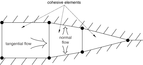
By default, there is no tangential flow of pore fluid within the cohesive element. To allow tangential flow, define a gap flow property in conjunction with the pore fluid material definition.

Newtonian Fluid

In the case of a Newtonian fluid the volume flow rate density vector is given by the expression

q d = - k t p ,

where kt is the tangential permeability (the resistance to the fluid flow), p is the pressure gradient along the cohesive element, and d is the gap opening.

In Abaqus the gap opening, d, is defined as

d = t c u r r - t o r i g + g i n i t ,

where tcurr and torig are the current and original cohesive element geometrical thicknesses, respectively; and ginit is the initial gap opening, which has a default value of 0.002.

Abaqus defines the tangential permeability, or the resistance to flow, according to Reynold's equation:

k t = d 3 12 μ ,

where μ is the fluid viscosity and d is the gap opening. You can also specify an upper limit on the value of kt.

Power Law Fluid

In the case of a power law fluid the constitutive relation is defined as

τ = K γ ˙ α ,

where τ is the shear stress, γ˙ is the shear strain rate, K is the fluid consistency, and α is the power law coefficient. Abaqus defines the tangential volume flow rate density as

q d = - ( 2 α 1 + 2 α ) ( 1 K ) 1 α ( d 2 ) 1 + 2 α α p 1 - α α p ,

where d is the gap opening.

Bingham Plastic Fluid

In the case of a Bingham plastic fluid the volume flow rate density vector is given by the expression

q d = ( 1 3 ) ( 1 K ) ( d 2 ) 3 p ( 1 2 τ 0 2 d p ) 2 ( 2 + 2 τ 0 d p ) ,

where K is the fluid consistency, τ 0 is the yield stress, and d is the gap opening. The unyielded fluid is modeled as a Newtonian fluid with viscosity equal to P τ × K , where P τ has a default value of 107.

Herschel-Bulkley Fluid

In the case of a Herschel-Bulkley fluid the volume flow rate density vector is given by the expression

q d = 2 [ ( α 1 + α ) ( α 1 + 2 α ) ] ( 1 K ) 1 α ( d 2 ) 1 + 2 α α p 1 α α ( 1 2 τ 0 d p ) 1 + α α ( 1 α + 1 + 2 τ 0 d p ) p ,

where K is the fluid consistency, α is the power law coefficient, τ 0 is the yield stress, and d is the gap opening. The unyielded fluid is modeled as a Newtonian fluid with viscosity equal to P τ × K , where P τ has a default value of 107.

Normal Flow across Gap Surfaces

You can permit normal flow by defining a fluid leak-off coefficient for the pore fluid material. This coefficient defines a pressure-flow relationship between the cohesive element's middle nodes and their adjacent surface nodes. The fluid leak-off coefficients can be interpreted as the permeability of a finite layer of material on the cohesive element surfaces, as shown in Figure 2.

Leak-off coefficient interpretation as a permeable layer.

The normal flow is defined as

q t = c t ( p i - p t )

and

q b = c b ( p i - p b ) ,

where qt and qb are the flow rates into the top and bottom surfaces, respectively; pi is the midface pressure; and pt and pb are the pore pressures on the top and bottom surfaces, respectively.

Defining Leak-off Coefficients as a Function of Temperature and Field Variables

You can optionally define leak-off coefficients as functions of temperature and field variables.

Defining Leak-off Coefficients in a User Subroutine

User subroutine UFLUIDLEAKOFF can also be used to define more complex leak-off behavior, including the ability to define a time accumulated resistance, or fouling, through the use of solution-dependent state variables.

Tangential and Normal Flow Combinations

Table 1 shows the permitted combinations of tangential and normal flow and the effects of each combination.

Table 1. Effects of flow property definition combinations.
  Normal flow is defined Normal flow is undefined
Tangential flow is defined Tangential and normal flow are modeled. Tangential flow is modeled. Pore pressure continuity is enforced between facing nodes in the cohesive element only when the element is closed. Otherwise, the surfaces are impermeable in the normal direction.
Tangential flow is undefined Normal flow is modeled. Tangential flow is not modeled. Pore pressure continuity is always enforced between facing nodes in the cohesive element.

Initially Open Elements

When the opening of the cohesive element is driven primarily by entry of fluid into the gap, you will have to define one or more elements as initially open, since tangential flow is possible only in an open element. Identify initially open elements as initial conditions.

Additional Considerations

Your use of cohesive element fluid properties and your property values can impact your solution in some cases.

Large Coefficient Values

You must make sure that the tangential permeability or fluid leak-off coefficients are not excessively large. If either coefficient is many orders of magnitude higher than the permeability in the adjacent continuum elements, matrix conditioning problems may occur, leading to solver singularities and unreliable results.

Use in Total Pore Pressure Simulations

Definition of tangential flow properties may result in inaccurate results if the total pore pressure formulation is used and the hydrostatic pressure gradient contributes significantly to the tangential flow in the gap. The total pore pressure formulation is invoked if you apply gravity distributed loads to all elements in the model. The results will be accurate if the hydrostatic pressure gradient (i.e., the gravity vector) is perpendicular to the cohesive element.

Output

The following output variables are available when flow is enabled in pore pressure cohesive elements:

GFVR

Gap fluid volume rate.

PFOPEN

Fracture opening.

LEAKVRT

Leak-off flow rate at element top.

ALEAKVRT

Accumulated leak-off flow volume at element top.

LEAKVRB

Leak-off flow rate at element bottom.

ALEAKVRB

Accumulated leak-off flow volume at element bottom.

FLDVEL

Material point fluid velocity.