If relative forces or motions in a connection exceed critical values, the
connector starts undergoing irreversible damage (degradation). Upon additional
loading there is further evolution of damage leading to eventual failure. If
damage has occurred, the force response in the connector component
i will change according to the following general
form:
where
is a scalar damage variable and
is the response in the available connector component of relative motion
i if damage were not present (effective response).
To define a connector damage mechanism, you specify the following:
a criterion for damage initiation; and
a damage evolution law that specifies how the damage variable
d evolves (optional).
Prior to damage initiation, d has a value of 0.0; thus,
the force response in the connector does not change. Once damage has been
initiated, the damage variable will monotonically evolve up to the maximum
value of 1.0 if damage evolution is specified. Complete failure occurs when
d = 1.0.
Abaqus
allows you to specify a maximum degradation value (the default value is 1.0);
damage evolution will stop when the damage variable reaches this value, and the
element will be deleted from the mesh by default. Alternatively, you can
specify that the damaged connector elements remain in the analysis with no
further damage evolution. The maximum degradation value is used to evaluate the
damaged stiffness in the remaining part of the analysis. This functionality is
discussed in detail in
Controlling Element Deletion and Maximum Degradation for Materials with Damage Evolution.
For connectors with purely elastic behavior, damage can be initiated and
evolved in one direction only. If damage was initiated in tension, it will
evolve in tension; if damage was initiated in compression, it will evolve in
compression. Once damage initiates in tension, it cannot be initiated in
compression and vice versa.
Defining Connector Damage Initiation
The degradation process in connectors initiates when forces or relative
motions in the connector satisfy certain criteria. Three different criteria
types can be used to trigger damage in connectors: criteria based on force,
plastic motion, or constitutive motion. Connector damage initiation criteria
for the available components of relative motion can be specified for each
component independently (uncoupled). Alternatively, connector damage initiation
criteria that couple all or some of the available components of relative motion
in the connector can be defined.
The damage initiation criterion can depend on temperature and field
variables. See
Input Syntax Rules
for further information about defining data as functions of temperature and
field variables.
Force-Based Damage Initiation Criterion
By default, the damage initiation criterion is specified in terms of
forces/moments in the connector. Elastic or rigid connector behavior must be
defined for the components involved in the initiation. You provide the lower
(compression) limit, ,
and the upper (tension) limit, ,
for the force/moment damage initiation values. If the force is outside the
range specified by the two limit values, damage is initiated. The output
variable CDIF can be used to monitor the proximity
to the damage initiation point.
Defining Uncoupled Force-Based Damage Initiation
For an uncoupled force-based damage initiation criterion, the connector
force in the specified component is compared to the specified limit values.
Damage is initiated when the force in the specified component
i, ,
is for the first time outside the range (
or ).
Defining Coupled Force-Based Damage Initiation
For a coupled force-based damage initiation criterion, a connector
potential, ,
must be specified to define an equivalent force magnitude (scalar). The
equivalent force magnitude is compared to the specified limit values to assess
damage initiation. Damage is initiated when the equivalent force magnitude,
,
is for the first time outside the range (
or ).
Plastic Motion–Based Damage Initiation Criterion
The damage initiation criterion can be specified in terms of an equivalent
relative plastic motion in the connector. You provide the relative equivalent
plastic displacement/rotation at which damage will be initiated as a function
of the relative equivalent plastic rate. The output variable
CDIP can be used to monitor the proximity to the
damage initiation point.
Defining Uncoupled Plastic Damage Initiation
For an uncoupled elastic-plastic or rigid plastic damage initiation
criterion, uncoupled connector plasticity in the specified component of
relative motion must be defined (see
Connector Plastic Behavior).
When the equivalent relative plastic motion as defined by the associated
plasticity definition is greater than the specified limit value for the first
time, damage is initiated.
Defining Coupled Plastic Damage Initiation
For a coupled elastic-plastic or rigid plastic damage initiation
criterion, coupled connector plasticity must be defined. The connector
potential used in the coupled connector plasticity function defines an
equivalent relative plastic motion. This equivalent relative plastic motion is
compared to the specified limit values to assess damage initiation. The
equivalent relative plastic motion at which damage is initiated can be a
function of the mode-mix ratio
(see
Connector Plastic Behavior).
The damage initiation criterion can be specified in terms of relative
constitutive displacements/rotations in the connector. You provide the lower
(compression) limit, ,
and the upper (tension) limit, ,
for the constitutive displacement/rotation damage initiation values. If the
motion is outside the range specified by the two limit values, damage is
initiated. The output variable CDIM can be used to
monitor the proximity to the damage initiation point.
For an uncoupled motion-based damage initiation criterion, the connector
relative constitutive motion in the specified component is compared to the
specified limit values. Damage is initiated when the relative constitutive
displacement/rotation in the specified component i,
,
is for the first time outside the range (
or ).
For a coupled motion-based damage initiation criterion, a connector
potential, ,
must be specified to define an equivalent motion magnitude (scalar), where
is the collection of
all available components of relative motion in the connector. The equivalent
motion magnitude is compared to the specified limit values to assess damage
initiation. Damage is initiated when the equivalent motion magnitude,
,
is for the first time outside the range (
or ).
Defining Connector Damage Evolution
Connector damage evolution specifies the evolution law for the damage
variable. Upon evolution, the connector response will be degraded. The
evolution of damage can be based on an energy dissipation criterion or on
relative (plastic) motions. In the motion-based criteria the damage variable,
d, can be defined as a linear, exponential, or tabular
function of relative motions.
The damage evolution law can depend on temperature and field variables. See
Input Syntax Rules
for further information about defining data as functions of temperature and
field variables.
Specifying the Affected Components
By default (i.e., the affected components are not specified explicitly),
only the elastic/rigid or elastic/rigid-plastic response in the connector will
be damaged. The response due to friction, damping, and stop/lock behavior will
not be degraded. For an uncoupled connector damage mechanism (uncoupled damage
initiation criterion), only the specified component of relative motion will
undergo damage. For coupled connector damage initiation, the components that
will be degraded by default are chosen as follows:
If a force-based or constitutive motion-based damage initiation
criterion is used, the intrinsic available components (1 through 6) that
ultimately contribute to the connector potential for damage initiation will be
affected.
If a plastic motion–based damage initiation criterion is used, the
intrinsic available components that ultimately contribute to the connector
potential used in the coupled plasticity definition will be affected.
Alternatively, you can specify the available components of relative motion
that will be affected by the damage evolution law directly. In this case the
entire connector response (elasto/rigid-plastic, friction, damping, constraint
forces and moments, etc.) in the affected components will be damaged.
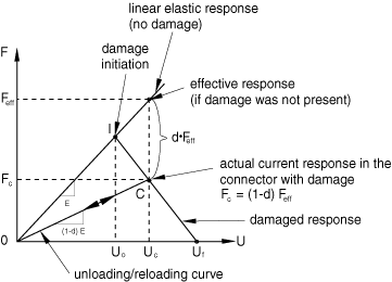
Defining a Motion-Based Linear Damage Evolution Law
The linear form of the damage evolution law is illustrated here in the
context of linear elasticity, although it can be used in any situation. Assume
that the connector response is linear elastic and that after damage initiation
a linear damage evolution is desired, as illustrated in
Figure 1.
Linear damage evolution law for linear elastic connector
behavior.
If damage were not specified, the response would be linear elastic (a
straight line passing through the origin). Assume that damage has initiated at
point I as triggered by a force-based or motion-based criterion, for example;
the corresponding constitutive motion at this point is
.
If the connector is loaded further such that the constitutive motion increases
to ,
the connector force response at point C becomes .
The response is diminished by
when compared to the effective response
(the elastic response with no damage). Thus, .
If unloading occurs at point C, the unloading curve of slope
is followed. As long as the constitutive motion does not exceed
,
the damage variable, d, stays constant at the value
obtained when point C is first reached. If further loading occurs, further
damage occurs until the ultimate failure motion, ,
is reached (d = 1) and the connector component loses the
ability to carry any load. Thus, one possible loading/unloading sequence is
OICOC.
The linear damage evolution law defines a truly linear damaged force
response only in the case of linear elastic or rigid behavior with optional
perfect plasticity. If nonlinear elasticity or plasticity with hardening are
defined for the damaged components, an approximate linear damaged response is
observed.
In Abaqus/Standard the damage force (instead of the damage variable) decays linearly when component-based
linear elasticity is defined with component-based damage. This behavior is different from
the behavior in Abaqus/Explicit, where the damage variable decays linearly.
Defining the Linear Evolution Law for a Force-Based or Constitutive Motion-Based Damage Initiation Criterion
If an uncoupled damage initiation criterion is used in component
i, you specify the difference between the constitutive
relative motion at ultimate failure, ,
and the constitutive relative motion at damage initiation,
,
in the specified component ().
If a coupled damage initiation criterion is used, an equivalent
constitutive relative motion, ,
must be defined for damage evolution purposes. A connector potential definition
is used to define .
You specify the difference between the equivalent motion at ultimate failure,
,
and the equivalent motion at damage initiation,
().
Defining the Linear Evolution Law for a Plastic Motion–Based Damage Initiation Criterion
You can specify the difference between the associated equivalent plastic
relative motion at ultimate failure, ,
and the associated equivalent plastic relative motion at damage initiation,
(),
as a function of the mode-mix ratio, ,
defined in
Connector Plastic Behavior.
The equivalent plastic relative motions are calculated from the associated
plasticity definition (either coupled or uncoupled).
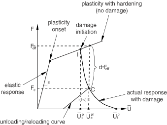
Defining a Motion-Based Exponential Damage Evolution Law
The exponential damage evolution law is illustrated in the context of a
linear elastic-plastic response with hardening, although it can be used in any
situation. The force response in a particular connector component is shown in
Figure 2.
Exponential damage evolution law for linear elastic-plastic connector
behavior with hardening.
Assume that damage is initiated at point I as triggered by a plastic
motion–based damage initiation criterion. If further loading occurs until point
C, the response is .
Unloading from point C occurs along the damaged elastic line of slope
.
Upon unloading/reloading, the damage variable remains constant until point C is
reached again. Further loading (beyond point C) leads to an increasingly
damaged response until the ultimate failure point, ,
is reached (d = 1). The damage variable
d is given by the following equation:
The damaged response will appear to be truly exponential only if either
linear elasticity or perfect plasticity is used. An approximate exponential
degradation is obtained if plasticity with hardening is present.
You specify the difference between the relative motions at ultimate failure
and at damage initiation and the exponential coefficient
.
The difference between the relative motions is interpreted in the same way as
described in
Defining a Motion-Based Linear Damage Evolution Law,
as follows:
If an uncoupled force-based or constitutive motion-based damage
initiation criterion is used, the difference between the relative motions at
ultimate failure and at damage initiation in the specified component
i, ,
is specified.
If a coupled force-based or constitutive motion-based damage initiation
criterion is used, an equivalent relative motion is defined using a connector
potential ().
The difference between the relative motions at ultimate failure and at damage
initiation, ,
is specified.
If a plastic motion–based damage initiation criterion is used, the
difference between the equivalent relative plastic motions at ultimate failure
and at damage initiation, ,
is specified. The equivalent plastic relative motion is calculated from the
associated plasticity definition. The data can also be functions of the
mode-mix ratio .
In the first two cases the equation for the damage variable is similar to
that given above for plastic motion–based damage initiation except that
(equivalent) constitutive relative motions are used instead of equivalent
relative plastic motions.
Defining a Motion-Based Tabular Damage Evolution Law
You can also specify the damage variable directly as a tabular function of
the differences between the relative motions at ultimate failure and the
relative motions at damage initiation. The differences between the relative
motions are interpreted in the same way as described in
Defining a Motion-Based Linear Damage Evolution Law,
as follows:
If an uncoupled force-based or constitutive motion-based damage
initiation criterion is used, the differences between the constitutive relative
motions at ultimate failure and at damage initiation in the specified component
i, ,
are used to define the tabular data.
If a coupled force-based or constitutive motion-based damage initiation
criterion is used, an equivalent relative motion is defined using a connector
potential ().
The differences between the relative motions at ultimate failure and at damage
initiation, ,
are used to define the tabular data.
If a plastic motion–based damage initiation criterion is used, the
differences between the equivalent relative plastic motions at ultimate failure
and at damage initiation, ,
are used. The equivalent plastic relative motion is calculated from the
associated plasticity definition. The tabular data can also be functions of the
mode-mix ratio .
Defining a Damage Evolution Law Using Post-Damage Initiation Dissipation Energies
This damage evolution law is illustrated in the context of nonlinear
elasticity, as shown in
Figure 3.
Post-damage initiation dissipation energy evolution law for nonlinear
elastic connector behavior.
Assume that damage is initiated at point I when the constitutive relative
motion is
as triggered by a force-based or a motion-based damage initiation criterion,
for example. The response at point C will be .
Unloading from point C occurs along the CO
curve, which is the original nonlinear elastic response curve
(OE) scaled down by the
()
factor. Damage remains constant on the unloading/reloading curve
(COC),
and it increases only if loading increases beyond point C.
Instantaneous failure can be specified upon initiation if
is specified as 0.0. In all other cases ultimate failure
(d = 1) would occur (in theory) at infinite motion since
an exponential-like response that asymptotically goes to zero is generated.
Abaqus
will set d = 1 when the damage dissipated energy reaches
0.99.
You specify the post-damage initiation dissipated energy at ultimate
failure, .
If a plastic motion–based initiation criterion is used,
can be specified as a function of the mode-mix ratio .
Using Multiple Damage Mechanisms
At most three uncoupled damage mechanisms (pairs of connector damage
initiation criteria and connector damage evolution laws) can be defined for
each available component of relative motion, one for each type of initiation
criterion (force, motion, and plastic motion). In addition, three coupled
damage mechanisms can be defined (one for each type of initiation criterion).
Coupled and uncoupled damage definitions can be combined; only one overall
damage variable per component will be used to damage the response in a
particular available component of relative motion. Only the overall damage will
be output.
Specifying the Contribution of Each Damage Mechanism
When several damage mechanisms are defined for the same connector behavior,
you can specify the contribution of each damage mechanism to the overall damage
effect for a particular component of relative motion. By default, the damage
value associated with a particular mechanism will be compared to the damage
values from any other damage mechanisms defined for the connector behavior, and
only the maximum value will be considered for the overall damage.
Alternatively, you can specify that the damage values for the mechanisms
associated with the connector behavior should be combined in a multiplicative
fashion to obtain the overall damage. See the last example below for an
illustration.
Examples
The examples that follow illustrate several methods for defining damage
mechanisms.
Uncoupled Damage
The following input could be used to define a simple uncoupled damage
mechanism:
Damage will initiate when the elastic force in component 1 is either smaller
than force_compress or larger than
force_tens. Only the elastic response in component 1
will be damaged. Since the dissipated energy specified for damage evolution is
0.0, the damage evolves catastrophically instantaneously after it has
initiated.
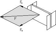
Coupled Rigid Plasticity with Plasticity-Based Damage
Referring to the spot weld in
Figure 4
for which coupled plasticity is defined in
Connector Plastic Behavior,
a plastic motion–based damage initiation and evolution with dependencies on the
mode-mix ratio can be specified as follows:
The equivalent plastic relative motion on the data lines is defined by the
associated coupled plasticity definition illustrated in
Connector Plastic Behavior.
For the damage evolution the post-damage-initiation equivalent plastic relative
motion should be specified. The second column in all the data lines represents
the mode-mix ratios as defined in
Connector Plastic Behavior.
In this particular case the mode-mix ratio is .
The data point at 0.0 comes from a pure “shear” experiment, and the data point
at 1.0 comes from a pure “normal” experiment. Data for the values in between
come from combined “shear-normal” experiments.
Coupled Rigid Plasticity with Force-Based Damage Initiation and Motion-Based Damage Evolution
Damage will be initiated when the force magnitude defined by the first
connector potential definition exceeds the specified value of 1.0. The scale
factors
and
in the first potential definition are used in this case to define a force
magnitude that would be 1.0 at damage initiation. A motion-based exponential
decay damage evolution law is chosen. The second connector potential definition
is associated with the connector damage evolution definition and defines an
equivalent motion, ,
in the connection. When the equivalent post-initiation motion,
(where
is
at damage initiation), reaches ,
ultimate failure occurs. All components (1 through 6) are affected in this case
since they all ultimately contribute to the first connector potential
definition (see
Defining Derived Components for Connector Elements
for the specific definitions associated with the
normal and shear
derived components).
Elastic-Plasticity with Four Competing Damage Mechanisms
This example illustrates how to specify the contributions of multiple damage
mechanisms to the overall damage effect and the components of relative motion
affected by the damage evolution law. Most of the data line entries or
parameters are not given for conciseness.
Four damage mechanisms (connector damage initiation/connector damage
evolution pairs) are specified: three uncoupled and one coupled. The first line
of each damage evolution definition establishes the components that will be
damaged by the mechanism. The overall damage in a particular component is
determined by contributions from all the mechanisms that affect that component.
For example, the overall damage in component 1, ,
is determined by the second, third, and fourth damage mechanisms as follows:
and
use multiplicative degradation; therefore, they are multiplied first:
.
uses maximum degradation, so
is compared to
and the minimum value is taken.
For example, assume that at a particular time t,
=0.5,
=0.3,
and =0.2
and at time ,
=0.6
(the only one increasing) while
and
stay the same. The overall damage variable gets closer to the ultimate damage
value faster when all three damage mechanisms are used than if we use only the
mechanism:
while
Complete failure occurs when
reaches 0.0.
,
where i refers to the
available component of relative motion. The overall damage variables for the
other components are determined as follows (based on the specified affected
components for each damage evolution law):
Maximum Degradation and Choice of Element Removal in Abaqus/Standard
Alternatively, you can specify that a connector element should remain in the
model even after the overall damage variable reaches .
In this case, once the overall damage variable reaches
,
the element stiffness remains constant at
times the undamaged stiffness.
Viscous Regularization in Abaqus/Standard
Damage causes a softening response in connector elements, which often leads
to convergence difficulties in an implicit code such as
Abaqus/Standard.
One technique for overcoming convergence difficulties is applying viscous
regularization to the constitutive response by introducing a viscous damage
variable, ,
as defined by the evolution equation
where
is the damage variable evaluated in the inviscid backbone model and
is the viscosity parameter representing the relaxation time. The damaged
response of the viscous material is given as
As a result of viscous regularization, the damped damage variable does not
obey the specified evolution law exactly (only the backbone damage variable
does).
Defining Connector Damage Behavior in Linear Perturbation Procedures
Damage cannot be initiated and damage variables do not evolve during linear
perturbation analyses. Consequently, during a linear perturbation step damage
is “frozen” in the state attained at the end of the previous general step.
Force-based connector damage initiation variable. In addition to the usual
six components associated with connector output variables,
CDIF includes the scalar
CDIFC, which is the damage initiation criterion
value associated with a coupled force-based damage initiation criterion.
CDIM
Motion-based connector damage initiation variable.
CDIM includes the scalar
CDIMC, which is the damage initiation criterion
value associated with a coupled motion-based damage initiation criterion.
CDIP
Plastic motion–based connector damage initiation variable.
CDIP includes the scalar
CDIPC, which is the damage initiation criterion
value associated with a coupled plastic motion–based damage initiation
criterion.