Shear Panel Elements

Shear panel elements:

  • are 4-node surface elements that transmit only shear forces along the elements edges (no normal forces);
  • have no bending stiffness;
  • are typically used together with truss elements or beam elements that help stabilize the structure;
  • can be used only with linear elastic material behavior;
  • are intended to be used in small-displacement analysis only (large-rotation effects are not included);
  • do not include thermal strain effects; and
  • do not include material/element-based viscous damping effects;

This page discusses:

Typical Applications

Shear panel elements are special surface elements for modeling thin reinforced plates and shells, such as thin skin panels in aircraft wings and fuselage structures. These elements can transmit shear forces only along their edges (see Figure 1). They cannot transmit normal forces, and they have no bending stiffness. The shear panel elements should not be used alone and should typically be used together with reinforcing truss or beam elements.
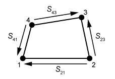
Shear flows along the edges of shear panel elements.

The elements have only displacement degrees of freedom. They are intended to be used only in small-displacement analyses. Large-rotation effects, thermal strain effects, and material/element-based viscous damping effects are not included. The elements can be used only with linear elastic material behavior.
Shear Panel Element Formulation

The shear panel element formulation is based on the work by Garvey (1951). For an arbitrary flat quadrilateral sheer panel element, the average shear flows along the element edges (see Figure 1) have the relationship

S21S43=S23S41,
where S21, S43, S23, and S41 denote the average shear flows along the element edges 12, 43, 23, and 41, respectively. The equivalent shear flow, q, of the element is defined as:
q2=S21S43=S23S41.

The shear strain, γ, associated with the equivalent shear flow, q, can be written as

γ=qGt,
where G is the shear modulus, and t is the element thickness. The strain energy of the element can be expressed as
E=12q2AGt,
where A is the element area. When the nodes of the element are not in a plane, the element calculations are based on nodes projected to a reference plane.

Element Normal Definition

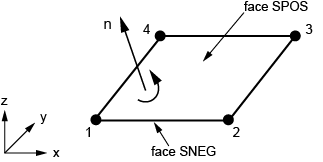
The "top" surface of a shear panel element is the surface in the positive normal direction (see Figure 2) and is called the SPOS face for contact definition. The "bottom" surface is in the negative direction along the normal and is called the SNEG face for contact definition.

Positive normals for shear panel elements.

Defining the Element's Section Properties

The section properties of shear panel elements must be defined using a general shell section definition. You must associate these properties with a region of your model.

Defining a Constant Section Thickness

You can define a constant section thickness as part of the section definition.

Defining a Variable Thickness Using Distributions

You can define a spatially varying thickness for shear panels using a distribution (Distribution Definition).

The distribution used to define shear panel thickness must have a default value. The default thickness is used by any shear panel element assigned to the shell general section that is not specifically assigned a value in the distribution.

Assigning a Material Definition to a Set of Shear Panel Elements

You must associate a material definition with each general shell section definition.

Defining Density for Shear Panel Elements

You can define additional mass per unit area for shear panel elements directly in the section definition.

This functionality is similar to the more general functionality of defining a nonstructural mass contribution (see Nonstructural Mass Definition.) The only difference between the two definitions is that the nonstructural mass contributes to the rotary inertia terms about the midsurface while the additional mass defined in the section definition does not.

References

  1. Garvey S. J.The Quadrilateral 'Shear' Panel: The Peculiar Stressing Problems Arising in the Structure of the Non-Rectangular Swept Wing,” Aircraft Engineering, vol. 23, pp. 134144, 1951.