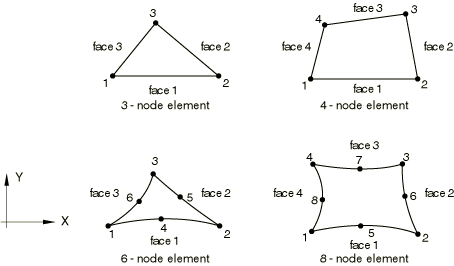
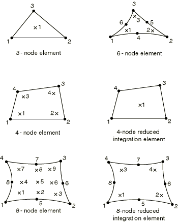
Two-Dimensional Solid Element Library

This section provides a reference to the two-dimensional solid elements available in Abaqus/Standard and Abaqus/Explicit.

This page discusses:

Element Types

Plane Strain Elements

CPE3

3-node linear

CPE3H(S)

3-node linear, hybrid with constant pressure

CPE4(S)

4-node bilinear

CPE4H(S)

4-node bilinear, hybrid with constant pressure

CPE4I(S)

4-node bilinear, incompatible modes

CPE4IH(S)

4-node bilinear, incompatible modes, hybrid with linear pressure

CPE4R

4-node bilinear, reduced integration with hourglass control

CPE4RH(S)

4-node bilinear, reduced integration with hourglass control, hybrid with constant pressure

CPE6(S)

6-node quadratic

CPE6H(S)

6-node quadratic, hybrid with linear pressure

CPE6M

6-node modified, with hourglass control

CPE6MH(S)

6-node modified, with hourglass control, hybrid with linear pressure

CPE8(S)

8-node biquadratic

CPE8H(S)

8-node biquadratic, hybrid with linear pressure

CPE8R(S)

8-node biquadratic, reduced integration

CPE8RH(S)

8-node biquadratic, reduced integration, hybrid with linear pressure

Active Degrees of Freedom

1, 2

Additional Solution Variables

The constant pressure hybrid elements have one additional variable relating to pressure, and the linear pressure hybrid elements have three additional variables relating to pressure.

Element types CPE4I and CPE4IH have five additional variables relating to the incompatible modes.

Element types CPE6M and CPE6MH have two additional displacement variables.

Plane Stress Elements

CPS3

3-node linear

CPS4(S)

4-node bilinear

CPS4I(S)

4-node bilinear, incompatible modes

CPS4R

4-node bilinear, reduced integration with hourglass control

CPS6(S)

6-node quadratic

CPS6M

6-node modified, with hourglass control

CPS8(S)

8-node biquadratic

CPS8R(S)

8-node biquadratic, reduced integration

Active Degrees of Freedom

1, 2

Additional Solution Variables

Element type CPS4I has four additional variables relating to the incompatible modes.

Element type CPS6M has two additional displacement variables.

Generalized Plane Strain Elements

CPEG3(S)

3-node linear triangle

CPEG3H(S)

3-node linear triangle, hybrid with constant pressure

CPEG4(S)

4-node bilinear quadrilateral

CPEG4H(S)

4-node bilinear quadrilateral, hybrid with constant pressure

CPEG4I(S)

4-node bilinear quadrilateral, incompatible modes

CPEG4IH(S)

4-node bilinear quadrilateral, incompatible modes, hybrid with linear pressure

CPEG4R(S)

4-node bilinear quadrilateral, reduced integration with hourglass control

CPEG4RH(S)

4-node bilinear quadrilateral, reduced integration with hourglass control, hybrid with constant pressure

CPEG6(S)

6-node quadratic triangle

CPEG6H(S)

6-node quadratic triangle, hybrid with linear pressure

CPEG6M(S)

6-node modified, with hourglass control

CPEG6MH(S)

6-node modified, with hourglass control, hybrid with linear pressure

CPEG8(S)

8-node biquadratic quadrilateral

CPEG8H(S)

8-node biquadratic quadrilateral, hybrid with linear pressure

CPEG8R(S)

8-node biquadratic quadrilateral, reduced integration

CPEG8RH(S)

8-node biquadratic quadrilateral, reduced integration, hybrid with linear pressure

Active Degrees of Freedom

1, 2 at all but the reference node

3, 4, 5 at the reference node

Additional Solution Variables

The constant pressure hybrid elements have one additional variable relating to pressure, and the linear pressure hybrid elements have three additional variables relating to pressure.

Element types CPEG4I and CPEG4IH have five additional variables relating to the incompatible modes.

Element types CPEG6M and CPEG6MH have two additional displacement variables.

Coupled Temperature-Displacement Plane Strain Elements

CPE3T

3-node linear displacement and temperature

CPE4T(S)

4-node bilinear displacement and temperature

CPE4HT(S)

4-node bilinear displacement and temperature, hybrid with constant pressure

CPE4RT

4-node bilinear displacement and temperature, reduced integration with hourglass control

CPE4RHT(S)

4-node bilinear displacement and temperature, reduced integration with hourglass control, hybrid with constant pressure

CPE6MT

6-node modified displacement and temperature, with hourglass control

CPE6MHT(S)

6-node modified displacement and temperature, with hourglass control, hybrid with constant pressure

CPE8T(S)

8-node biquadratic displacement, bilinear temperature

CPE8HT(S)

8-node biquadratic displacement, bilinear temperature, hybrid with linear pressure

CPE8RT(S)

8-node biquadratic displacement, bilinear temperature, reduced integration

CPE8RHT(S)

8-node biquadratic displacement, bilinear temperature, reduced integration, hybrid with linear pressure

Active Degrees of Freedom

1, 2, 11 at corner nodes

1, 2 at midside nodes of second-order elements in Abaqus/Standard

1, 2, 11 at midside nodes of modified displacement and temperature elements in Abaqus/Standard

Additional Solution Variables

The constant pressure hybrid elements have one additional variable relating to pressure, and the linear pressure hybrid elements have three additional variables relating to pressure.

Element types CPE6MT and CPE6MHT have two additional displacement variables and one additional temperature variable.

Coupled Temperature-Displacement Plane Stress Elements

CPS3T

3-node linear displacement and temperature

CPS4T(S)

4-node bilinear displacement and temperature

CPS4RT

4-node bilinear displacement and temperature, reduced integration with hourglass control

CPS6MT

6-node modified displacement and temperature, with hourglass control

CPS8T(S)

8-node biquadratic displacement, bilinear temperature

CPS8RT(S)

8-node biquadratic displacement, bilinear temperature, reduced integration

Active Degrees of Freedom

1, 2, 11 at corner nodes

1, 2 at midside nodes of second-order elements in Abaqus/Standard

1, 2, 11 at midside nodes of modified displacement and temperature elements in Abaqus/Standard

Additional Solution Variables

Element type CPS6MT has two additional displacement variables and one additional temperature variable.

Coupled Temperature-Displacement Generalized Plane Strain Elements

CPEG3T(S)

3-node linear displacement and temperature

CPEG3HT(S)

3-node linear displacement and temperature, hybrid with constant pressure

CPEG4T(S)

4-node bilinear displacement and temperature

CPEG4HT(S)

4-node bilinear displacement and temperature, hybrid with constant pressure

CPEG4RT(S)

4-node bilinear displacement and temperature, reduced integration with hourglass control

CPEG4RHT(S)

4-node bilinear displacement and temperature, reduced integration with hourglass control, hybrid with constant pressure

CPEG6MT(S)

6-node modified displacement and temperature, with hourglass control

CPEG6MHT(S)

6-node modified displacement and temperature, with hourglass control, hybrid with constant pressure

CPEG8T(S)

8-node biquadratic displacement, bilinear temperature

CPEG8HT(S)

8-node biquadratic displacement, bilinear temperature, hybrid with linear pressure

CPEG8RHT(S)

8-node biquadratic displacement, bilinear temperature, reduced integration, hybrid with linear pressure

Active Degrees of Freedom

1, 2, 11 at corner nodes

1, 2 at midside nodes of second-order elements

1, 2, 11 at midside nodes of modified displacement and temperature elements

3, 4, 5 at the reference node

Additional Solution Variables

The constant pressure hybrid elements have one additional variable relating to pressure, and the linear pressure hybrid elements have three additional variables relating to pressure.

Element types CPEG6MT and CPEG6MHT have two additional displacement variables and one additional temperature variable.

Diffusive Heat Transfer or Mass Diffusion Elements

DC2D3(S)

3-node linear

DC2D4(S)

4-node linear

DC2D6(S)

6-node quadratic

DC2D8(S)

8-node biquadratic

Active Degrees of Freedom

11

Additional Solution Variables

None.

Forced Convection/Diffusion Elements

DCC2D4(S)

4-node

DCC2D4D(S)

4-node with dispersion control

Active Degrees of Freedom

11

Additional Solution Variables

None.

Coupled Thermal-Electrical Elements

DC2D3E(S)

3-node linear

DC2D4E(S)

4-node linear

DC2D6E(S)

6-node quadratic

DC2D8E(S)

8-node biquadratic

Active Degrees of Freedom

9, 11

Additional Solution Variables

None.

Pore Pressure Plane Strain Elements

CPE4P(S)

4-node bilinear displacement and pore pressure

CPE4PH(S)

4-node bilinear displacement and pore pressure, hybrid with constant pressure stress

CPE4RP(S)

4-node bilinear displacement and pore pressure, reduced integration with hourglass control

CPE4RPH(S)

4-node bilinear displacement and pore pressure, reduced integration with hourglass control, hybrid with constant pressure

CPE6MP(S)

6-node modified displacement and pore pressure, with hourglass control

CPE6MPH(S)

6-node modified displacement and pore pressure, with hourglass control, hybrid with linear pressure

CPE8P(S)

8-node biquadratic displacement, bilinear pore pressure

CPE8PH(S)

8-node biquadratic displacement, bilinear pore pressure, hybrid with linear pressure stress

CPE8RP(S)

8-node biquadratic displacement, bilinear pore pressure, reduced integration

CPE8RPH(S)

8-node biquadratic displacement, bilinear pore pressure, reduced integration, hybrid with linear pressure stress

Active Degrees of Freedom

1, 2, 8 at corner nodes

1, 2 at midside nodes for all elements except CPE6MP and CPE6MPH, which also have degree of freedom 8 active at midside nodes

Additional Solution Variables

The constant pressure hybrid elements have one additional variable relating to the effective pressure stress, and the linear pressure hybrid elements have three additional variables relating to the effective pressure stress to permit fully incompressible material modeling.

Element types CPE6MP and CPE6MPH have two additional displacement variables and one additional pore pressure variable.

Coupled Temperature–Pore Pressure Plane Strain Elements

CPE4PT(S)

4-node bilinear displacement, pore pressure, and temperature

CPE4PHT(S)

4-node bilinear displacement, pore pressure, and temperature; hybrid with constant pressure stress

CPE4RPT(S)

4-node bilinear displacement, pore pressure, and temperature; reduced integration

CPE4RPHT(S)

4-node bilinear displacement, pore pressure, and temperature; reduced integration, hybrid with constant pressure stress

Active Degrees of Freedom

1, 2, 8, 11 at corner nodes

Additional Solution Variables

The constant pressure stress hybrid elements have one additional variable relating to the effective pressure stress to permit fully incompressible material modeling.

Acoustic Elements

AC2D3

3-node linear

AC2D4(S)

4-node bilinear

AC2D4R(E)

4-node bilinear, reduced integration with hourglass control

AC2D6(S)

6-node quadratic

AC2D8(S)

8-node biquadratic

Active Degrees of Freedom

8

Additional Solution Variables

None.

Piezoelectric Plane Strain Elements

CPE3E(S)

3-node linear

CPE4E(S)

4-node bilinear

CPE6E(S)

6-node quadratic

CPE8E(S)

8-node biquadratic

CPE8RE(S)

8-node biquadratic, reduced integration

Active Degrees of Freedom

1, 2, 9

Additional Solution Variables

None.

Piezoelectric Plane Stress Elements

CPS3E(S)

3-node linear

CPS4E(S)

4-node bilinear

CPS6E(S)

6-node quadratic

CPS8E(S)

8-node biquadratic

CPS8RE(S)

8-node biquadratic, reduced integration

Active Degrees of Freedom

1, 2, 9

Additional Solution Variables

None.

Electromagnetic Elements

EMC2D3(S)

3-node zero-order

EMC2D4(S)

4-node zero-order

Active Degrees of Freedom

Magnetic vector potential (for more information, see Boundary Conditions and Boundary Conditions).

Additional Solution Variables

None.

Nodal Coordinates Required

X, Y

Element Property Definition

For all elements except generalized plane strain elements, you must provide the element thickness; by default, unit thickness is assumed.

For generalized plane strain elements, you must provide three values: the initial length of the axial material fiber through the reference node, the initial value of Δϕx (in radians), and the initial value of Δϕy (in radians). If you do not provide these values, Abaqus assumes the default values of one unit as the initial length and zero for Δϕx and Δϕy. In addition, you must define the reference point for generalized plane strain elements.

Element-Based Loading

Distributed Loads

Distributed loads are available for all elements with displacement degrees of freedom. They are specified as described in Distributed Loads.

*dload
  1. Load ID (*DLOAD): BX
  2. FL−3
  3. Body force in global X-direction.

  1. Load ID (*DLOAD): BY
  2. FL−3
  3. Body force in global Y-direction.

  1. Load ID (*DLOAD): BXNU
  2. FL−3
  3. Nonuniform body force in global X-direction with magnitude supplied via user subroutine DLOAD in Abaqus/Standard and VDLOAD in Abaqus/Explicit.

  1. Load ID (*DLOAD): BYNU
  2. FL−3
  3. Nonuniform body force in global Y-direction with magnitude supplied via user subroutine DLOAD in Abaqus/Standard  and VDLOAD in Abaqus/Explicit.

  1. Load ID (*DLOAD): CENT (S)
  2. FL−4(ML−3T−2)
  3. Centrifugal load (magnitude is input as ρω2, where ρ is the mass density per unit volume, ω is the angular velocity). Not available for pore pressure elements.

  1. Load ID (*DLOAD): CENTRIF (S)
  2. T−2
  3. Centrifugal load (magnitude is input as ω2, where ω is the angular velocity).

  1. Load ID (*DLOAD): CORIO (S)
  2. FL−4T (ML−3T−1)
  3. Coriolis force (magnitude is input as ρω, where ρ is the mass density per unit volume, ω is the angular velocity). Not available for pore pressure elements.

  1. Load ID (*DLOAD): GRAV
  2. LT−2
  3. Gravity loading in a specified direction (magnitude is input as acceleration).

  1. Load ID (*DLOAD): HPn (S)
  2. FL−2
  3. Hydrostatic pressure on face n, linear in global Y.

  1. Load ID (*DLOAD): Pn
  2. FL−2
  3. Pressure on face n.

  1. Load ID (*DLOAD): PnNU
  2. FL−2
  3. Nonuniform pressure on face n with magnitude supplied via user subroutine DLOAD in Abaqus/Standard and VDLOAD in Abaqus/Explicit.

  1. Load ID (*DLOAD): ROTA (S)
  2. T−2
  3. Rotary acceleration load (magnitude is input as α, where α is the rotary acceleration).

  1. Load ID (*DLOAD): SBF (E)
  2. FL−5T2
  3. Stagnation body force in global X- and Y-directions.

  1. Load ID (*DLOAD): SPn (E)
  2. FL−4T2
  3. Stagnation pressure on face n.

  1. Load ID (*DLOAD): TRSHRn
  2. FL−2
  3. Shear traction on face n.

  1. Load ID (*DLOAD): TRSHRnNU (S)
  2. FL−2
  3. Nonuniform shear traction on face n with magnitude and direction supplied via user subroutine UTRACLOAD.

  1. Load ID (*DLOAD): TRVECn
  2. FL−2
  3. General traction on face n.

  1. Load ID (*DLOAD): TRVECnNU (S)
  2. FL−2
  3. Nonuniform general traction on face n with magnitude and direction supplied via user subroutine UTRACLOAD.

  1. Load ID (*DLOAD): VBF (E)
  2. FL−4T
  3. Viscous body force in global X- and Y-directions.

  1. Load ID (*DLOAD): VPn (E)
  2. FL−3T
  3. Viscous pressure on face n, applying a pressure proportional to the velocity normal to the face and opposing the motion.

Foundations

Foundations are available for Abaqus/Standard elements with displacement degrees of freedom. They are specified as described in Element Foundations.

*foundation
  1. Load ID (*FOUNDATION): Fn (S)
  2. FL−3
  3. Elastic foundation on face n.

Distributed Heat Fluxes

Distributed heat fluxes are available for all elements with temperature degrees of freedom. They are specified as described in Thermal Loads.

*dflux
  1. Load ID (*DFLUX): BF
  2. JL−3T−1
  3. Heat body flux per unit volume.

  1. Load ID (*DFLUX): BFNU
  2. JL−3T−1
  3. Nonuniform heat body flux per unit volume with magnitude supplied via user subroutine DFLUX in Abaqus/Standard and VDFLUX in Abaqus/Explicit.

  1. Load ID (*DFLUX): Sn
  2. JL−2T−1
  3. Heat surface flux per unit area into face n.

  1. Load ID (*DFLUX): SnNU
  2. JL−2T−1
  3. Nonuniform heat surface flux per unit area into face n with magnitude supplied via user subroutine DFLUX in Abaqus/Standard and VDFLUX in Abaqus/Explicit.

Film Conditions

Film conditions are available for all elements with temperature degrees of freedom. They are specified as described in Thermal Loads.

*film
  1. Load ID (*FILM): Fn
  2. JL−2T−1θ−1
  3. Film coefficient and sink temperature (units of θ) provided on face n.

  1. Load ID (*FILM): FnNU (S)
  2. JL−2T−1θ−1
  3. Nonuniform film coefficient and sink temperature (units of θ) provided on face n with magnitude supplied via user subroutine FILM.

Radiation Types

Radiation conditions are available for all elements with temperature degrees of freedom. They are specified as described in Thermal Loads.

*radiate
  1. Load ID (*RADIATE): Rn
  2. Dimensionless
  3. Emissivity and sink temperature (units of θ) provided on face n.

Distributed Flows

Distributed flows are available for all elements with pore pressure degrees of freedom. They are specified as described in Pore Fluid Flow.

*flow
  1. Load ID (*FLOW): Qn (S)
  2. F−1L3T−1
  3. Seepage coefficient and reference sink pore pressure (units of FL−2) provided on face n.

  1. Load ID (*FLOW): QnD (S)
  2. F−1L3T−1
  3. Drainage-only seepage coefficient provided on face n.

  1. Load ID (*FLOW): QnNU (S)
  2. F−1L3T−1
  3. Nonuniform seepage coefficient and reference sink pore pressure (units of FL−2) provided on face n with magnitude supplied via user subroutine FLOW.

*dflow
  1. Load ID (*DFLOW): Sn (S)
  2. LT−1
  3. Prescribed pore fluid effective velocity (outward from the face) on face n.

  1. Load ID (*DFLOW): SnNU (S)
  2. LT−1
  3. Nonuniform prescribed pore fluid effective velocity (outward from the face) on face n with magnitude supplied via user subroutine DFLOW.

Distributed Impedances

Distributed impedances are available for all elements with acoustic pressure degrees of freedom. They are specified as described in Acoustic and Shock Loads.

*impedance
  1. Load ID (*IMPEDANCE): In
  2. None
  3. Name of the impedance property that defines the impedance on face n.

Electric Fluxes

Electric fluxes are available for piezoelectric elements. They are specified as described in Piezoelectric Analysis.

*decharge
  1. Load ID (*DECHARGE): EBF (S)
  2. CL−3
  3. Body flux per unit volume.

  1. Load ID (*DECHARGE): ESn (S)
  2. CL−2
  3. Prescribed surface charge on face n.

Distributed Electric Current Densities

Distributed electric current densities are available for coupled thermal-electrical elements, coupled thermal-electrical-structural elements, and electromagnetic elements. They are specified as described in Coupled Thermal-Electrical Analysis, Fully Coupled Thermal-Electrical-Structural Analysis, and Eddy Current Analysis.

*decurrent
  1. Load ID (*DECURRENT): CBF (S)
  2. CL−3T−1
  3. Volumetric current source density.

  1. Load ID (*DECURRENT): CSn (S)
  2. CL−2T−1
  3. Current density on face n.

  1. Load ID (*DECURRENT): CJ (S)
  2. CL−2T−1
  3. Volume current density vector in an eddy current analysis.

Distributed Concentration Fluxes

Distributed concentration fluxes are available for mass diffusion elements. They are specified as described in Mass Diffusion Analysis.

*dflux
  1. Load ID (*DFLUX): BF (S)
  2. PT−1
  3. Concentration body flux per unit volume.

  1. Load ID (*DFLUX): BFNU (S)
  2. PT−1
  3. Nonuniform concentration body flux per unit volume with magnitude supplied via user subroutine DFLUX.

  1. Load ID (*DFLUX): Sn (S)
  2. PLT−1
  3. Concentration surface flux per unit area into face n.

  1. Load ID (*DFLUX): SnNU (S)
  2. PLT−1
  3. Nonuniform concentration surface flux per unit area into face n with magnitude supplied via user subroutine DFLUX.

Surface-Based Loading

Distributed Loads

Surface-based distributed loads are available for all elements with displacement degrees of freedom. They are specified as described in Distributed Loads.

*dsload
  1. Load ID (*DSLOAD): HP (S)
  2. FL−2
  3. Hydrostatic pressure on the element surface, linear in global Y.

  1. Load ID (*DSLOAD): P
  2. FL−2
  3. Pressure on the element surface.

  1. Load ID (*DSLOAD): PNU
  2. FL−2
  3. Nonuniform pressure on the element surface with magnitude supplied via user subroutine DLOAD in Abaqus/Standard and VDLOAD in Abaqus/Explicit.

  1. Load ID (*DSLOAD): SP (E)
  2. FL−4T2
  3. Stagnation pressure on the element surface.

  1. Load ID (*DSLOAD): TRSHR
  2. FL−2
  3. Shear traction on the element surface.

  1. Load ID (*DSLOAD): TRSHRNU (S)
  2. FL−2
  3. Nonuniform shear traction on the element surface with magnitude and direction supplied via user subroutine UTRACLOAD.

  1. Load ID (*DSLOAD): TRVEC
  2. FL−2
  3. General traction on the element surface.

  1. Load ID (*DSLOAD): TRVECNU (S)
  2. FL−2
  3. Nonuniform general traction on the element surface with magnitude and direction supplied via user subroutine UTRACLOAD.

  1. Load ID (*DSLOAD): VP (E)
  2. FL−3T
  3. Viscous pressure on the element surface. The viscous pressure is proportional to the velocity normal to the element surface and opposing the motion.

Distributed Heat Fluxes

Surface-based heat fluxes are available for all elements with temperature degrees of freedom. They are specified as described in Thermal Loads.

*dsflux
  1. Load ID (*DSFLUX): S
  2. JL−2T−1
  3. Heat surface flux per unit area into the element surface.

  1. Load ID (*DSFLUX): SNU
  2. JL−2T−1
  3. Nonuniform heat surface flux per unit area applied on the element surface with magnitude supplied via user subroutine DFLUX in Abaqus/Standard and VDFLUX in Abaqus/Explicit.

Film Conditions

Surface-based film conditions are available for all elements with temperature degrees of freedom. They are specified as described in Thermal Loads.

*sfilm
  1. Load ID (*SFILM): F
  2. JL−2T−1θ−1
  3. Film coefficient and sink temperature (units of θ) provided on the element surface.

  1. Load ID (*SFILM): FNU (S)
  2. JL−2T−1θ−1
  3. Nonuniform film coefficient and sink temperature (units of θ) provided on the element surface with magnitude supplied via user subroutine FILM.

Radiation Types

Surface-based radiation conditions are available for all elements with temperature degrees of freedom. They are specified as described in Thermal Loads.

*sradiate
  1. Load ID (*SRADIATE): R
  2. Dimensionless
  3. Emissivity and sink temperature (units of θ) provided on the element surface.

Distributed Flows

Surface-based flows are available for all elements with pore pressure degrees of freedom. They are specified as described in Pore Fluid Flow.

*sflow
  1. Load ID (*SFLOW): Q (S)
  2. F−1L3T−1
  3. Seepage coefficient and reference sink pore pressure (units of FL−2) provided on the element surface.

  1. Load ID (*SFLOW): QD (S)
  2. F−1L3T−1
  3. Drainage-only seepage coefficient provided on the element surface.

  1. Load ID (*SFLOW): QNU (S)
  2. F−1L3T−1
  3. Nonuniform seepage coefficient and reference sink pore pressure (units of FL−2) provided on the element surface with magnitude supplied via user subroutine FLOW.

*dsflow
  1. Load ID (*DSFLOW): S (S)
  2. LT−1
  3. Prescribed pore fluid effective velocity outward from the element surface.

  1. Load ID (*DSFLOW): SNU (S)
  2. LT−1
  3. Nonuniform prescribed pore fluid effective velocity outward from the element surface with magnitude supplied via user subroutine DFLOW.

Distributed Impedances

Surface-based impedances are available for all elements with acoustic pressure degrees of freedom. They are specified as described in Acoustic and Shock Loads.

Incident Wave Loading

Surface-based incident wave loads are available for all elements with displacement degrees of freedom or acoustic pressure degrees of freedom. They are specified as described in Acoustic and Shock Loads. If the incident wave field includes a reflection off a plane outside the boundaries of the mesh, this effect can be included.

Electric Fluxes

Surface-based electric fluxes are available for piezoelectric elements. They are specified as described in Piezoelectric Analysis.

*dsecharge
  1. Load ID (*DSECHARGE): ES (S)
  2. CL−2
  3. Prescribed surface charge on the element surface.

Distributed Electric Current Densities

Surface-based electric current densities are available for coupled thermal-electrical elements, coupled thermal-electrical-structural elements, and electromagnetic elements. They are specified as described in Coupled Thermal-Electrical Analysis, Fully Coupled Thermal-Electrical-Structural Analysis, and Eddy Current Analysis.

*dsecurrent
  1. Load ID (*DSECURRENT): CS (S)
  2. CL−2T−1
  3. Current density applied on the element surface.

  1. Load ID (*DSECURRENT): CK (S)
  2. CL−1T−1
  3. Surface current density vector in an eddy current analysis.

Element Output

For most elements output is in global directions unless a local coordinate system is assigned to the element through the section definition (Orientations) in which case output is in the local coordinate system (which rotates with the motion in large-displacement analysis). See State storage for details.

Stress, Strain, and Other Tensor Components

Stress and other tensors (including strain tensors) are available for elements with displacement degrees of freedom. All tensors have the same components. For example, the stress components are as follows:

S11

XX, direct stress.

S22

YY, direct stress.

S33

ZZ, direct stress (not available for plane stress elements).

S12

XY, shear stress.

Heat Flux Components

Available for elements with temperature degrees of freedom.

HFL1

Heat flux in the X-direction.

HFL2

Heat flux in the Y-direction.

Pore Fluid Velocity Components

Available for elements with pore pressure degrees of freedom.

FLVEL1

Pore fluid effective velocity in the X-direction.

FLVEL2

Pore fluid effective velocity in the Y-direction.

Mass Concentration Flux Components

Available for elements with normalized concentration degrees of freedom.

MFL1

Concentration flux in the X-direction.

MFL2

Concentration flux in the Y-direction.

Electrical Potential Gradient

Available for elements with electrical potential degrees of freedom.

EPG1

Electrical potential gradient in the X-direction.

EPG2

Electrical potential gradient in the Y-direction.

Electrical Flux Components

Available for piezoelectric elements.

EFLX1

Electrical flux in the X-direction.

EFLX2

Electrical flux in the Y-direction.

Electrical Current Density Components

Available for coupled thermal-electrical elements.

ECD1

Electrical current density in the X-direction.

ECD2

Electrical current density in the Y-direction.

Electrical Field Components

Available for electromagnetic elements in an eddy current analysis.

EME1

Electric field in the X-direction.

EME2

Electric field in the Y-direction.

Magnetic Flux Density Components

Available for electromagnetic elements.

EMB3

Magnetic flux density in the Z-direction.

Magnetic Field Components

Available for electromagnetic elements.

EMH3

Magnetic field in the Z-direction.

Eddy Current Density Components in an Eddy Current Analysis

Available for electromagnetic elements in an eddy current analysis.

EMCD1

Eddy current density in the X-direction.

EMCD2

Eddy current density in the Y-direction.

Applied Volume Current Density Components in an Eddy Current or Magnetostatic Analysis

Available for electromagnetic elements in an eddy current or magnetostatic analysis.

EMCDA1

Applied volume current density in the X-direction.

EMCDA2

Applied volume current density in the Y-direction.

Node Ordering and Face Numbering on Elements


For generalized plane strain elements, the reference node associated with each element (where the generalized plane strain degrees of freedom are stored) is not shown. The reference node should be the same for all elements in any given connected region so that the bounding planes are the same for that region. Different regions may have different reference nodes. The number of the reference node is not incremented when the elements are generated incrementally (see Creating Elements from Existing Elements by Generating Them Incrementally).

Table 1. Triangular element faces
Face 1 1 – 2 face
Face 2 2 – 3 face
Face 3 3 – 1 face
Table 2. Quadrilateral element faces
Face 1 1 – 2 face
Face 2 2 – 3 face
Face 3 3 – 4 face
Face 4 4 – 1 face