|
Element Types
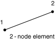
Link Elements
- GK3D2
-
2-node, three-dimensional gasket element
- GK3D2N
-
2-node, three-dimensional gasket element with thickness-direction behavior
only
Active Degrees of Freedom
1 for gasket elements with thickness-direction behavior only.
1, 2, 3 for other gasket elements.
Additional Solution Variables
None.
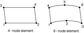
Line Elements
- GK3D4L
-
4-node, three-dimensional line gasket element
- GK3D4LN
-
4-node, three-dimensional line gasket element with thickness-direction
behavior only
- GK3D6L
-
6-node, three-dimensional line gasket element
- GK3D6LN
-
6-node, three-dimensional line gasket element with thickness-direction
behavior only
Active Degrees of Freedom
1 for gasket elements with thickness-direction behavior only.
1, 2, 3 for other gasket elements.
Additional Solution Variables
None.
Area Elements
- GK3D6
-
6-node, three-dimensional gasket element
- GK3D6N
-
6-node, three-dimensional gasket element with thickness-direction behavior
only
- GK3D8
-
8-node, three-dimensional gasket element
- GK3D8N
-
8-node, three-dimensional gasket element with thickness-direction behavior
only
- GK3D12M
-
12-node, three-dimensional gasket element
- GK3D12MN
-
12-node, three-dimensional gasket element with thickness-direction behavior
only
- GK3D18
-
18-node, three-dimensional gasket element
- GK3D18N
-
18-node, three-dimensional gasket element with thickness-direction behavior
only
Active Degrees of Freedom
1 for gasket elements with thickness-direction behavior only.
1, 2, 3 for other gasket elements.
Additional Solution Variables
None.
Coupled Temperature-Displacement Area Elements
- GK3D6T
-
6-node, three-dimensional displacement and temperature gasket element
- GK3D6TN
-
6-node, three-dimensional displacement and temperature gasket element with
thickness-direction behavior only
- GK3D8T
-
8-node, three-dimensional displacement and temperature gasket element
- GK3D8TN
-
8-node, three-dimensional displacement and temperature gasket element with
thickness-direction behavior only
Active Degrees of Freedom
1, 11 for gasket elements with thickness-direction behavior only.
1, 2, 3, 11 for other gasket elements.
Additional Solution Variables
None.
Nodal Coordinates Required
Element Property Definition
You must
define the element's initial gap and initial void, as well as the
cross-sectional area (for link elements) or width (for line elements).
You can specify the thickness direction as part of the gasket section
definition or by specifying a normal direction at the nodes; you can specify
the element thickness as part of the gasket section definition. Otherwise,
Abaqus/Standard
will calculate the thickness direction and the thickness. For link elements the
thickness direction is the direction from the first to the second node and the
thickness is the distance between the nodes. For line elements the thickness
direction is the direction from the bottom node to the top node associated with
the integration point and the thicknesses are the distances between these same
bottom and top nodes. For area elements the thickness direction is based on the
midsurface of the element and the thicknesses at the integration points are
based on the nodal positions. See
Defining the Gasket Element's Initial Geometry
for more details.
Element-Based Loading
Element Output
GK3D2 Elements
- S11
-
Pressure or thickness-direction force in the gasket element.
- CS11
-
Contact pressure in the gasket element (only available if S11 is a force and the gasket response is not defined using a
material model).
- S12
-
Shear stress or shear force.
- S13
-
Shear stress or shear force.
- E11
-
Gasket closure if the gasket response is defined directly using a gasket
behavior model; strain if the gasket response is defined using a material
model.
- E12
-
Shear motion if the gasket response is defined directly using a gasket
behavior model; strain if the gasket response is defined using a material
model.
- E13
-
Shear motion if the gasket response is defined directly using a gasket
behavior model; strain if the gasket response is defined using a material
model.
- NE11
-
Effective thickness-direction strain in the gasket element.
- NE12
-
Effective shear strain.
- NE13
-
Effective shear strain.
GK3D2N Elements
- S11
-
Pressure or thickness-direction force in the gasket element.
- CS11
-
Contact pressure in the gasket element (only available if S11 is a force and the gasket response is not defined using a
material model.)
- E11
-
Gasket closure if the gasket response is defined directly using a gasket
behavior model; strain if the gasket response is defined using a material
model.
- NE11
-
Effective thickness-direction strain in the gasket element.
Line Elements with Thickness-Direction Behavior Only
- S11
-
Pressure or thickness-direction force per unit length in the gasket element.
- CS11
-
Contact pressure in the gasket element (only available if S11 is a force per unit length and the gasket response is not
defined using a material model).
- E11
-
Gasket closure if the gasket response is defined directly using a gasket
behavior model; strain if the gasket response is defined using a material
model.
- NE11
-
Effective thickness-direction strain in the gasket element.
Other Line Elements
- S11
-
Pressure or thickness-direction force per unit length in the gasket element.
- CS11
-
Contact pressure in the gasket element (only available if S11 is a force per unit length and the gasket response is not
defined using a material model).
- S22
-
Direct membrane stress.
- S12
-
Shear stress or shear force per unit length.
- S13
-
Shear stress or shear force per unit length.
- E11
-
Gasket closure if the gasket response is defined directly using a gasket
behavior model; strain if the gasket response is defined using a material
model.
- E22
-
Direct membrane strain.
- E12
-
Shear motion if the gasket response is defined directly using a gasket
behavior model; strain if the gasket response is defined using a material
model.
- E13
-
Shear motion if the gasket response is defined directly using a gasket
behavior model; strain if the gasket response is defined using a material
model.
- NE11
-
Effective thickness-direction strain in the gasket element.
- NE22
-
Direct membrane strain.
- NE12
-
Effective shear strain.
- NE13
-
Effective shear strain.
Area Elements with Thickness-Direction Behavior Only
- S11
-
Pressure in the gasket element.
- E11
-
Gasket closure if the gasket response is defined directly using a gasket
behavior model; strain if the gasket response is defined using a material
model.
- NE11
-
Effective thickness-direction strain in the gasket element.
Other Area Elements
- S11
-
Pressure in the gasket element.
- S22
-
Direct membrane stress.
- S33
-
Direct membrane stress.
- S12
-
Transverse shear stress.
- S13
-
Transverse shear stress.
- S23
-
Membrane shear stress.
- E11
-
Gasket closure if the gasket response is defined directly using a gasket
behavior model; strain if the gasket response is defined using a material
model.
- E22
-
Direct membrane strain.
- E33
-
Direct membrane strain.
- E12
-
Transverse shear motion if the gasket response is defined directly using a
gasket behavior model; strain if the gasket response is defined using a
material model.
- E13
-
Transverse shear motion if the gasket response is defined directly using a
gasket behavior model; strain if the gasket response is defined using a
material model.
- E23
-
Membrane shear strain.
- NE11
-
Effective thickness-direction strain in the gasket element.
- NE22
-
Direct membrane strain.
- NE33
-
Direct membrane strain.
- NE12
-
Effective shear strain.
- NE13
-
Effective shear strain.
- NE12
-
Membrane shear strain.
Node Ordering and Face Numbering on Elements
Link Elements
Line Elements
Area Elements
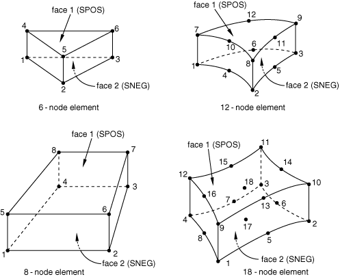
Table 1. 6-node element
| Face 1 (SPOS)
|
4 – 6 – 5 face
|
| Face 2 (SNEG)
|
1 – 2 – 3 face
|
Table 2. 8-node element
| Face 1 (SPOS)
|
5 – 8 – 7 – 6 face
|
| Face 2 (SNEG)
|
1 – 2 – 3 – 4 face
|
Table 3. 12-node element
| Face 1 (SPOS)
|
7 – 12 – 9 – 11 – 8 – 10 face
|
| Face 2 (SNEG)
|
1 – 4 – 2 – 5 – 3 – 6 face
|
Table 4. 18-node element
| Face 1 (SPOS)
|
9 – 16 – 12 – 15 – 11 – 14 – 10 – 13
face
|
| Face 2 (SNEG)
|
1 – 5 – 2 – 6 – 3 – 7 – 4 – 8 face
|
Numbering of Integration Points for Output
Link Elements
Line Elements
Area Elements
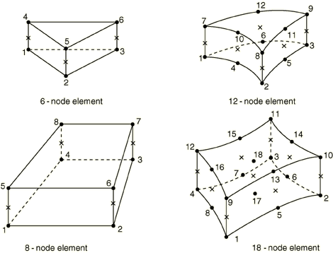
Integration points are indicated with an X and have the same numbers as the
bottom face nodes, except that the point between nodes 17 and 18 in the 18-node
gasket element is integration point number 9.
|