|
Element Types
Stress/Displacement Elements
- STRI3(S)
-
3-node triangular facet thin shell
- S3
-
3-node triangular general-purpose shell, finite membrane strains (identical
to element S3R)
- S3R
-
3-node triangular general-purpose shell, finite membrane strains (identical
to element S3)
- S3RS(E)
-
3-node triangular shell, small membrane strains
- STRI65(S)
-
6-node triangular thin shell, using five degrees of freedom per node
- S4
-
4-node general-purpose shell, finite membrane strains
- S4R
-
4-node general-purpose shell, reduced integration with hourglass control,
finite membrane strains
- S4RS(E)
-
4-node, reduced integration, shell with hourglass control, small membrane
strains
- S4RSW(E)
-
4-node, reduced integration, shell with hourglass control, small membrane
strains, warping considered in small-strain formulation
- S4R5(S)
-
4-node thin shell, reduced integration with hourglass control, using five
degrees of freedom per node
- S8R(S)
-
8-node doubly curved thick shell, reduced integration
- S8R5(S)
-
8-node doubly curved thin shell, reduced integration, using five degrees of
freedom per node
- S9R5(S)
-
9-node doubly curved thin shell, reduced integration, using five degrees of
freedom per node
Active Degrees of Freedom
1, 2, 3, 4, 5, 6 for STRI3, S3R, S3RS, S4, S4R, S4RS, S4RSW, S8R
1, 2, 3 and two in-surface rotations for STRI65, S4R5, S8R5, S9R5 at most nodes
1, 2, 3, 4, 5, 6 for STRI65, S4R5, S8R5, S9R5 at any node that
-
has a boundary condition on a rotational degree of freedom;
-
is involved in a multi-point constraint that uses rotational degrees of
freedom;
-
is attached to a beam or to a shell element that uses six degrees of
freedom at all nodes (such as S4R, S8R, STRI3, etc.);
-
is a point where different elements have different surface normals
(user-specified normal definitions or normal definitions created by
Abaqus
because the surface is folded); or
-
is loaded with moments.
Additional Solution Variables
Element type S8R5 has three displacement and two rotation variables at an
internally generated midbody node.
Heat Transfer Elements
- DS3(S)
-
3-node triangular shell
- DS4(S)
-
4-node quadrilateral shell
- DS6(S)
-
6-node triangular shell
- DS8(S)
-
8-node quadrilateral shell
Additional Solution Variables
None.
Coupled Temperature-Displacement Elements
- S3T(S)
-
3-node triangular general-purpose shell, finite membrane strains, bilinear
temperature in the shell surface (identical to element S3RT)
- S3RT
-
3-node triangular general-purpose shell, finite membrane strains, bilinear
temperature in the shell surface (for
Abaqus/Standard
it is identical to element S3T )
- S4T(S)
-
4-node general-purpose shell, finite membrane strains, bilinear temperature
in the shell surface
- S4RT
-
4-node general-purpose shell, reduced integration with hourglass control,
finite membrane strains, bilinear temperature in the shell surface
- S8RT(S)
-
8-node thick shell, biquadratic displacement, bilinear temperature in the
shell surface
Active Degrees of Freedom
1, 2, 3, 4, 5, 6 at all nodes
11, 12, 13, etc. (temperatures through the thickness as described in
Choosing a Shell Element)
at all nodes for S3T, S3RT, S4T, and S4RT; and at the corner nodes only for S8RT
Additional Solution Variables
None.
Nodal Coordinates Required
and, optionally for shells with displacement degrees of freedom in
Abaqus/Standard,
,
the direction cosines of the shell normal at the node.
Element Property Definition
Element-Based Loading
Distributed Loads
Distributed loads are available for all elements with displacement
degrees of freedom. They are specified as described in
Distributed Loads.
Body forces, centrifugal loads, and Coriolis forces must be given as
force per unit area if the equivalent section properties are specified directly
as part of the general shell section definition.
*dload
- Load ID (*DLOAD): BX
- FL−3
-
Body force (give magnitude as force per unit volume) in the global
X-direction.
- Load ID (*DLOAD): BY
- FL−3
-
Body force (give magnitude as force per unit volume) in the global
Y-direction.
- Load ID (*DLOAD): BZ
- FL−3
-
Body force (give magnitude as force per unit volume) in the global
Z-direction.
- Load ID (*DLOAD): BXNU
- FL−3
-
Nonuniform body force (give magnitude as force per unit volume) in the
global X-direction, with magnitude supplied via user
subroutine
DLOAD in
Abaqus/Standard
and
VDLOAD in
Abaqus/Explicit.
- Load ID (*DLOAD): BYNU
- FL−3
-
Nonuniform body force (give magnitude as force per unit volume) in the
global Y-direction, with magnitude supplied via user
subroutine
DLOAD in
Abaqus/Standard
and
VDLOAD in
Abaqus/Explicit.
- Load ID (*DLOAD): BZNU
- FL−3
-
Nonuniform body force (give magnitude as force per unit volume) in the
global Z-direction, with magnitude supplied via user
subroutine
DLOAD in
Abaqus/Standard
and
VDLOAD in
Abaqus/Explicit.
- Load ID (*DLOAD): CENT(S)
- FL−4
(ML−3T−2)
-
Centrifugal load (magnitude defined as ,
where
is the mass density and
is the angular speed).
- Load ID (*DLOAD): CENTRIF(S)
- T−2
-
Centrifugal load (magnitude is input as ,
where
is the angular speed).
- Load ID (*DLOAD): CORIO(S)
- FL−4T
(ML−3T−1)
-
Coriolis force (magnitude input ,
where
is the mass density and
is the angular speed). The load stiffness due to Coriolis loading is not
accounted for in direct steady-state dynamics analysis.
- Load ID (*DLOAD): EDLDn
- FL−1
-
General traction on edge n.
- Load ID (*DLOAD): EDLDnNU(S)
- FL−1
-
Nonuniform general traction on edge n with
magnitude and direction supplied via user subroutine
UTRACLOAD.
- Load ID (*DLOAD): EDMOMn
- F
-
Moment on edge n.
- Load ID (*DLOAD): EDMOMnNU(S)
- F
-
Nonuniform moment on edge n with magnitude
supplied via user subroutine
UTRACLOAD.
- Load ID (*DLOAD): EDNORn
- FL−1
-
Normal traction on edge n.
- Load ID (*DLOAD): EDNORnNU(S)
- FL−1
-
Nonuniform normal traction on edge n with
magnitude supplied via user subroutine
UTRACLOAD.
- Load ID (*DLOAD): EDSHRn
- FL−1
-
Shear traction on edge n.
- Load ID (*DLOAD): EDSHRnNU(S)
- FL−1
-
Nonuniform shear traction on edge n with
magnitude supplied via user subroutine
UTRACLOAD.
- Load ID (*DLOAD): EDTRAn
- FL−1
-
Transverse traction on edge n.
- Load ID (*DLOAD): EDTRAnNU(S)
- FL−1
-
Nonuniform transverse traction on edge n with
magnitude supplied via user subroutine
UTRACLOAD.
- Load ID (*DLOAD): GRAV
- LT−2
-
Gravity loading in a specified direction (magnitude is input as
acceleration).
- Load ID (*DLOAD): HP(S)
- FL−2
-
Hydrostatic pressure applied to the element reference surface and linear in
global Z. The pressure is positive in the direction of the
positive element normal.
- Load ID (*DLOAD): P
- FL−2
-
Pressure applied to the element reference surface. The pressure is positive
in the direction of the positive element normal.
- Load ID (*DLOAD): PNU
- FL−2
-
Nonuniform pressure applied to the element reference surface with magnitude
supplied via user subroutine
DLOAD in
Abaqus/Standard
and
VDLOAD in
Abaqus/Explicit.
The pressure is positive in the direction of the positive element normal.
- Load ID (*DLOAD): ROTA(S)
- T−2
-
Rotary acceleration load (magnitude is input as ,
where
is the rotary acceleration).
- Load ID (*DLOAD): ROTDYNF(S)
- T−1
-
Rotordynamic load (magnitude is input as ,
where
is the angular velocity).
- Load ID (*DLOAD): SBF(E)
- FL−5T
-
Stagnation body force in global X-,
Y-, and Z-directions.
- Load ID (*DLOAD): SP(E)
- FL−4T2
-
Stagnation pressure applied to the element reference surface.
- Load ID (*DLOAD): TRSHR
- FL−2
-
Shear traction on the element reference surface.
- Load ID (*DLOAD): TRSHRNU(S)
- FL−2
-
Nonuniform shear traction on the element reference surface with magnitude
and direction supplied via user subroutine
UTRACLOAD.
- Load ID (*DLOAD): TRVEC
- FL−2
-
General traction on the element reference surface.
- Load ID (*DLOAD): TRVECNU(S)
- FL−2
-
Nonuniform general traction on the element reference surface with magnitude
and direction supplied via user subroutine
UTRACLOAD.
- Load ID (*DLOAD): VBF(E)
- FL−4T
-
Viscous body force in global X-,
Y-, and Z-directions.
- Load ID (*DLOAD): VP(E)
- FL−3T
-
Viscous surface pressure. The viscous pressure is proportional to the
velocity normal to the element face and opposing the motion.
Foundations
Foundations are available for
Abaqus/Standard
elements with displacement degrees of freedom. They are specified as described
in
Element Foundations.
*foundation
- Load ID (*FOUNDATION): F(S)
- FL−3
-
Elastic foundation in the direction of the shell normal.
Distributed Heat Fluxes
Distributed heat fluxes are available for elements with temperature
degrees of freedom. They are specified as described in
Thermal Loads.
*dflux
- Load ID (*DFLUX): BF(S)
- JL−3 T−1
-
Body heat flux per unit volume.
- Load ID (*DFLUX): BFNU(S)
- JL−3 T−1
-
Nonuniform body heat flux per unit volume with magnitude supplied via user
subroutine
DFLUX.
- Load ID (*DFLUX):
MBFNU
(S)
-
JT−1
-
Nonuniform moving or stationary concentrated heat fluxes with magnitudes supplied
via user subroutine UMDFLUX.
- Load ID (*DFLUX): SNEG(S)
- JL−2 T−1
-
Surface heat flux per unit area into the bottom face of the element.
- Load ID (*DFLUX): SPOS(S)
- JL−2 T−1
-
Surface heat flux per unit area into the top face of the element.
- Load ID (*DFLUX): SNEGNU(S)
- JL−2
T−1
-
Nonuniform surface heat flux per unit area into the bottom face of the
element with magnitude supplied via user subroutine
DFLUX.
- Load ID (*DFLUX): SPOSNU(S)
- JL−2
T−1
-
Nonuniform surface heat flux per unit area into the top face of the element
with magnitude supplied via user subroutine
DFLUX.
Film Conditions
Film
conditions are available for elements with temperature degrees of freedom. They
are specified as described in
Thermal Loads.
*film
- Load ID (*FILM): FNEG(S)
- JL−2 T−1−1
-
Film coefficient and sink temperature (units of )
provided on the bottom face of the element.
- Load ID (*FILM): FPOS(S)
- JL−2 T−1−1
-
Film coefficient and sink temperature (units of )
provided on the top face of the element.
- Load ID (*FILM): FNEGNU(S)
- JL−2
T−1−1
-
Nonuniform film coefficient and sink temperature (units of
)
provided on the bottom face of the element with magnitude supplied via user
subroutine
FILM.
- Load ID (*FILM): FPOSNU(S)
- JL−2
T−1−1
-
Nonuniform film coefficient and sink temperature (units of
)
provided on the top face of the element with magnitude supplied via user
subroutine
FILM.
- Load ID (*FILM): FFS(S)
- JL−2 T−1−1
-
Film coefficient and sink temperature (units of )
provided on the top and bottom faces of the element.
- Load ID (*FILM): FFSNU(S)
- JL−2 T−1−1
-
Nonuniform film coefficient and sink temperature (units of
)
provided on the top and bottom faces of the element with magnitude supplied via
user subroutine.
Radiation Types
Radiation conditions are available for elements with temperature degrees
of freedom. They are specified as described in
Thermal Loads.
*radiate
- Load ID (*RADIATE): RNEG(S)
- Dimensionless
-
Emissivity and sink temperature (units of )
provided for the bottom face of the shell.
- Load ID (*RADIATE): RPOS(S)
- Dimensionless
-
Emissivity and sink temperature (units of )
provided for the top face of the shell.
- Load ID (*RADIATE): RFS(S)
- Dimensionless
-
Emissivity and sink temperature (units of )
provided for the top and bottom faces of the shell.
Surface-Based Loading
Distributed Loads
Surface-based distributed loads are available for all elements with
displacement degrees of freedom. They are specified as described in
Distributed Loads.
*dsload
- Load ID (*DSLOAD): EDLD
- FL−1
-
General traction on edge-based surface.
- Load ID (*DSLOAD): EDLDNU(S)
- FL−1
-
Nonuniform general traction on edge-based surface with magnitude and
direction supplied via user subroutine
UTRACLOAD.
- Load ID (*DSLOAD): EDMOM
- F
-
Moment on edge-based surface.
- Load ID (*DSLOAD): EDMOMNU(S)
- F
-
Nonuniform moment on edge-based surface with magnitude supplied via user
subroutine
UTRACLOAD.
- Load ID (*DSLOAD): EDNOR
- FL−1
-
Normal traction on edge-based surface.
- Load ID (*DSLOAD): EDNORNU(S)
- FL−1
-
Nonuniform normal traction on edge-based surface with magnitude supplied via
user subroutine
UTRACLOAD.
- Load ID (*DSLOAD): EDSHR
- FL−1
-
Shear traction on edge-based surface.
- Load ID (*DSLOAD): EDSHRNU(S)
- FL−1
-
Nonuniform shear traction on edge-based surface with magnitude supplied via
user subroutine
UTRACLOAD.
- Load ID (*DSLOAD): EDTRA
- FL−1
-
Transverse traction on edge-based surface.
- Load ID (*DSLOAD): EDTRANU(S)
- FL−1
-
Nonuniform transverse traction on edge-based surface with magnitude supplied
via user subroutine
UTRACLOAD.
- Load ID (*DSLOAD): HP(S)
- FL−2
-
Hydrostatic pressure on the element reference surface and linear in global
Z. The pressure is positive in the direction opposite to
the surface normal.
- Load ID (*DSLOAD): P
- FL−2
-
Pressure on the element reference surface. The pressure is positive in the
direction opposite to the surface normal.
- Load ID (*DSLOAD): PNU
- FL−2
-
Nonuniform pressure on the element reference surface with magnitude supplied
via user subroutine
DLOAD in
Abaqus/Standard
and
VDLOAD in
Abaqus/Explicit.
The pressure is positive in the direction opposite to the surface normal.
- Load ID (*DSLOAD): SP(E)
- FL−4T2
-
Stagnation pressure applied to the element reference surface.
- Load ID (*DSLOAD): TRSHR
- FL−2
-
Shear traction on the element reference surface.
- Load ID (*DSLOAD): TRSHRNU(S)
- FL−2
-
Nonuniform shear traction on the element reference surface with magnitude
and direction supplied via user subroutine
UTRACLOAD.
- Load ID (*DSLOAD): TRVEC
- FL−2
-
General traction on the element reference surface.
- Load ID (*DSLOAD): TRVECNU(S)
- FL−2
-
Nonuniform general traction on the element reference surface with magnitude
and direction supplied via user subroutine
UTRACLOAD.
- Load ID (*DSLOAD): VP(E)
- FL−3T
-
Viscous surface pressure. The viscous pressure is proportional to the
velocity normal to the element face and opposing the motion.
Distributed Heat Fluxes
Surface-based distributed heat fluxes are available for elements with
temperature degrees of freedom. They are specified as described in
Thermal Loads.
*dsflux
- Load ID (*DSFLUX): S(S)
- JL−2 T−1
-
Surface heat flux per unit area into the element surface.
- Load ID (*DSFLUX): SNU(S)
- JL−2 T−1
-
Nonuniform surface heat flux per unit area into the element surface with
magnitude supplied via user subroutine
DFLUX.
Film Conditions
Surface-based film conditions are available for elements with temperature
degrees of freedom. They are specified as described in
Thermal Loads.
*sfilm
- Load ID (*SFILM): F(S)
- JL−2 T−1−1
-
Film coefficient and sink temperature (units of )
provided on the element surface.
- Load ID (*SFILM): FNU(S)
- JL−2 T−1−1
-
Nonuniform film coefficient and sink temperature (units of
)
provided on the element surface with magnitude supplied via user subroutine
FILM.
Radiation Types
Surface-based radiation conditions are available for elements with
temperature degrees of freedom. They are specified as described in
Thermal Loads.
*sradiate
- Load ID (*SRADIATE): R(S)
- Dimensionless
-
Emissivity and sink temperature (units of )
provided for the element surface.
Incident Wave Loading
Element Output
If
a local coordinate system is not assigned to the element, the stress/strain
components, as well as the section forces/strains, are in the default
directions on the surface defined by the convention given in
Conventions.
If a local coordinate system is assigned to the element through the section
definition (Orientations),
the stress/strain components and the section forces/strains are in the surface
directions defined by the local coordinate system. In
large-displacement problems with elements that allow finite membrane strains in
Abaqus/Standard
and in all problems in
Abaqus/Explicit,
the local directions defined in the reference configuration are rotated into
the current configuration by the average material
rotation.
Stress, Strain, and Other Tensor Components
Stress and other tensors (including strain tensors) are available for
elements with displacement degrees of freedom. All tensors have the same
components. For example, the stress components are as follows:
- S11
-
Local
direct stress.
- S22
-
Local
direct stress.
- S12
-
Local
shear stress.
Section Forces, Moments, and Transverse Shear Forces
Available for elements with displacement degrees of freedom.
- SF1
-
Direct membrane force per unit width in local 1-direction.
- SF2
-
Direct membrane force per unit width in local 2-direction.
- SF3
-
Shear membrane force per unit width in local 1–2 plane.
- SF4
-
Transverse shear force per unit width in local 1-direction (available only
for S3/S3R, S3RS, S4, S4R, S4RS, S4RSW, S8R, and S8RT).
- SF5
-
Transverse shear force per unit width in local 2-direction (available only
for S3/S3R, S3RS, S4, S4R, S4RS, S4RSW, S8R, and S8RT).
- SM1
-
Bending moment force per unit width about local 2-axis.
- SM2
-
Bending moment force per unit width about local 1-axis.
- SM3
-
Twisting moment force per unit width in local 1–2 plane.
The section force and moment resultants per unit length in the normal basis
directions in a given shell section of thickness h can be
defined on this basis as
where
is the offset of the reference surface from the midsurface.
The section force SF6, which is the integral of
through the shell thickness, is reported only for finite-strain shell elements
and is zero because of the plane stress constitutive assumption. The total
number of attributes written to the results file for finite-strain shell
elements is 9; SF6 is the sixth attribute.
Average Section Stresses
Available for elements with displacement degrees of freedom.
- SSAVG1
-
Average membrane stress in local 1-direction.
- SSAVG2
-
Average membrane stress in local 2-direction.
- SSAVG3
-
Average membrane stress in local 1–2 plane.
- SSAVG4
-
Average transverse shear stress in local 1-direction.
- SSAVG5
-
Average transverse shear stress in local 2-direction.
The average section stresses are defined as
where h is the current section thickness.
Section Strains, Curvatures, and Transverse Shear Strains
Available for elements with displacement degrees of freedom.
- SE1
-
Direct membrane strain in local 1-direction.
- SE2
-
Direct membrane strain in local 2-direction.
- SE3
-
Shear membrane strain in local 1–2 plane.
- SE4
-
Transverse shear strain in the local 1-direction (available only for S3/S3R, S3RS, S4, S4R, S4RS, S4RSW, S8R, and S8RT).
- SE5
-
Transverse shear strain in the local 2-direction (available only for S3/S3R, S3RS, S4, S4R, S4RS, S4RSW, S8R, and S8RT).
- SE6
-
Strain in the thickness direction (available only for S3/S3R, S3RS, S4, S4R, S4RS, and S4RSW).
- SK1
-
Curvature change about local 2-axis.
- SK2
-
Curvature change about local 1-axis.
- SK3
-
Surface twist in local 1–2 plane.
The local directions are defined in
About Shell Elements.
Shell Thickness
- STH
-
Shell thickness, which is the current section thickness for S3/S3R, S3RS, S4, S4R, S4RS, and S4RSW elements.
Transverse Shear Stress Estimates
Available for S3/S3R, S3RS, S4, S4R, S4RS, S4RSW, S8R, and S8RT elements. - TSHR13
-
13-component of transverse shear stress.
- TSHR23
-
23-component of transverse shear stress.
Estimates of the transverse shear stresses are available at section
integration points as output variables TSHR13 or TSHR23 for both Simpson's rule and Gauss quadrature. For Simpson's
rule output of variables TSHR13 or TSHR23 should be requested at nondefault section points, since the
default output is at section point 1 of the shell section where the transverse
shear stresses vanish. For the small-strain elements in
Abaqus/Explicit,
transverse shear stress distributions are assumed constant for non-composite
sections and piecewise constant for composite sections; therefore, transverse
shear stresses at integration points should be interpreted accordingly.
For element type S4 the transverse shear calculation is performed at the center of
the element and assumed constant over the element. Hence, transverse shear
strain, force, and stress will not vary over the area of the element.
For numerically integrated shell sections (with the exception of
small-strain shells in
Abaqus/Explicit),
estimates of the interlaminar shear stresses in composite sections—i.e., the
transverse shear stresses at the interface between two composite layers—can be
obtained only by using Simpson's rule. With Gauss quadrature no section
integration point exists at the interface between composite layers.
Unlike the S11, S22, and S12 in-plane stress components, transverse shear stress components TSHR13 and TSHR23 are not calculated from the constitutive behavior at points
through the shell section. They are estimated by matching the elastic strain
energy associated with shear deformation of the shell section with that based
on piecewise quadratic variation of the transverse shear stress across the
section, under conditions of bending about one axis (see
Transverse shear stiffness in composite shells and offsets from the midsurface).
Therefore, interlaminar shear stress calculation is supported only when each
layer of the shell section is defined using an elastic material model or a
user-defined material model with the elastic transverse shear moduli defined.
If you specify the transverse shear stiffness values, interlaminar shear stress
output is not available.
Heat Flux Components
Available for elements with temperature degrees of freedom.
- HFL1
-
Heat flux in local 1-direction.
- HFL2
-
Heat flux in local 2-direction.
- HFL3
-
Heat flux in local 3-direction.
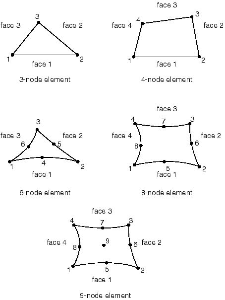
Node Ordering on Elements
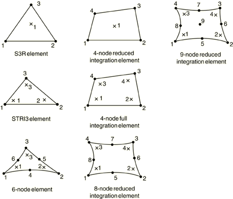
Numbering of Integration Points for Output
Stress/Displacement Analysis
Heat Transfer Analysis
|