Abaqus/Explicit provides two algorithms for modeling contact and interaction problems: the general contact
algorithm and the contact pair algorithm. See About Contact Interactions for
a comparison of the two algorithms. This section describes how to include general contact in
an Abaqus/Explicit analysis, how to specify the regions of the model that might be involved in general contact
interactions, and how to obtain output from a general contact analysis.
The general contact algorithm in
Abaqus/Explicit:
is specified as part of the model or history definition of the model;
allows very simple definitions of contact with very few restrictions
on the types of surfaces involved;
uses sophisticated tracking algorithms to ensure that proper contact
conditions are enforced efficiently;
can be used simultaneously with the contact pair algorithm (that is, some interactions can be
modeled with the general contact algorithm, while others are modeled with the contact pair
algorithm);
can be used with two-dimensional, axisymmetric, and three-dimensional
surfaces;
can be used only in mechanical finite-sliding contact analyses; and
does not support kinematic constraint enforcement (contact constraints
are enforced with the penalty method).
A convenient method of specifying the contact domain is using cropped
surfaces. Such surfaces can be used to perform “contact in a box” by using a
contact domain that is enclosed in a specified rectangular box in the original
configuration. For more information, see
Operating on Surfaces.
In addition,
Abaqus/Explicit
automatically defines an all-inclusive surface that is convenient for
prescribing the contact domain, as discussed later in this section. The
all-inclusive automatically defined surface includes all element-based surface
facets as well as all analytical rigid surfaces and surfaces on all Eulerian
materials.
The general contact algorithm generates contact forces to resist
node-into-face, node-into-analytical rigid surface, and edge-into-edge contact
penetrations. The primary mechanism for enforcing contact is node-to-face
contact (the only mechanism used in the contact pair algorithm). If analytical
rigid surfaces are present in the contact domain, the general contact algorithm
also enforces node-to-analytical rigid surface contact.
General contact can be used for a two-dimensional (plane strain, plane
stress, or axisymmetric) model, in which case node-into-face and
node-into-analytical rigid surface contact is considered.
Considerations for Edge-to-Edge Contact
The general contact algorithm also considers edge-to-edge contact, which is
very effective in enforcing contact that cannot be detected as penetrations of
nodes into faces. For example, contact between beam segments and shell
perimeter edges (see
Figure 1)
usually is detected only as edge-to-edge contact.
General contact domain, including edge-to-edge contact.
The terminology “contact edges” refers to feature edges of surface facets (on both shells and
solids) as well as to segments representing beam and truss elements. The contact edges
representing beam and truss elements have a circular cross-section, regardless of the
actual cross-section of the beam or truss element. The radius of a contact edge
representing a truss element is derived from the cross-sectional area specified on the
truss section definition (it is equal to the radius of a solid circular section with an
equivalent cross-sectional area). For beams with circular cross-sections, the radius of
the contact edge is equivalent to the section radius. For beams with noncircular
cross-sections, the radius of the contact edge is equal to the radius of a circumscribed
circle around the section. If connected edges have different radii, a nodal radius is
first computed as the minimum radius of the adjacent contact edges, and the radius of the
edge cross-section is interpolated linearly over the length of the contact edge from the
nodal values. Shell element edges reflect the shell thickness in the normal direction and
do not extend past the perimeter (similar to shell nodes and facets). Some numerical
rounding of features occurs for both node-to-facet and edge-to-edge contact.
To model contact between edges that are not cylindrical in shape, surface elements can be
attached to the edge nodes using surface-based tie constraints and node-to-face contact
can be defined between the surface elements (see Surface Elements). This
technique is useful for modeling geometric details important to the contact definition
that are not modeled with the underlying element geometry. Surface elements can also be
defined around shell elements in which Abaqus has reduced the contact thickness (that is, if the thickness exceeds the surface facet
edge lengths or diagonal lengths) so that the true surface thickness can be modeled.
However, using surface elements with general contact requires a physically reasonable mass
to be associated with the surface element nodes, and care must be taken not to alter the
bulk mass properties when transferring mass to the surface elements from the underlying
elements.
By default, when a surface is used in a general contact interaction, all applicable facets,
analytical rigid surfaces, nodes, perimeter edges, currently active feature edges, and
beam and truss segments are included in the contact definition. You can control which
feature edges are considered for edge-to-edge contact, as discussed in Assigning Surface Properties for General Contact in Abaqus/Explicit.
Contact Surface Representation for Beams
Figure 2
shows examples of beam element profile rendering for portions of beams with circular and
rectangular cross-sections. These beams are modeled with several beam elements on either
side of a kink. By default, Abaqus/Explicit uses a circular cross-section contact surface representation for beams, regardless of
the actual cross-section shape. For noncircular beam element cross-sections, the default
circumferential representation for contact encompasses the actual cross-section. Default
contact surface representations for both beams of Figure 2 are
identical and approximately correspond to the image on the left in Figure 2,
except for the addition of a smooth transition at the kink. The default contact
representation for beams involves contact nodes co-located with beam nodes and contact
edges associated with beam reference edges that pass through nodes of individual beam
elements; it does not involve contact faces on beams.Beam element profile rendering for circular versus rectangular cross-section
beams.
An alternative contact surface representation method for beams leads to a more accurate
contact representation of noncircular beams. This method uses an automatically generated
internal mesh of contact faces, nodes, and edges (such as shown in Figure 3).
Beams with circular cross-sections have the same contact surface representation (involving
contact nodes and contact edges only) for the default and alternative contact surface
representation methods. For the alternative contact surface representation method,
internal nodes are positioned at vertices of the cross-section at axial locations of each
original beam node. The motion of each of these internal nodes is driven by the
corresponding beam node (via a rigid connection). The internal contact faces, nodes, and
edges generated by Abaqus/Explicit are not available for postprocessing, but the shape they form closely resembles the
beam mesh with beam profile rendering activated. Internal mesh representations of beam contact surface.
Simulating contact among the beams shown in Figure 4
calls for the alternative contact surface representation. Both node-to-surface and
edge-to-edge contact can occur among contact nodes, faces, and edges of such a
simulation.Beams with various cross-sections.
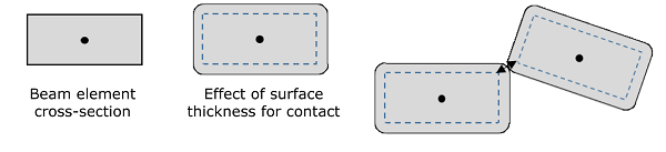
Assigning a nonzero surface thickness for contact (see Surface Thickness) to an alternative beam surface representation has the effect of expanding the contact
cross-section and rounding the corners (without influencing the beam stiffness), as shown
in Figure 5.Effect of surface thickness for a rectangular beam cross-section.
Eulerian-Lagrangian Contact
The general contact algorithm also enforces contact between Eulerian
materials and Lagrangian surfaces. This algorithm automatically compensates for
mesh size discrepancies to prevent penetration of Eulerian material through the
Lagrangian surface. The all-inclusive surface that is defined by
Abaqus/Explicit
can be used to enforce contact between all Eulerian materials and all
Lagrangian bodies in a model; you can also specify individual Eulerian surfaces
in the contact domain (see
Eulerian Surface Definition).
Eulerian-Lagrangian contact is enforced only for Lagrangian surfaces defined on
solid and shell elements. Other surface types, such as beam edges and
analytical rigid surfaces, are ignored. Contact interactions between Eulerian
materials and interactions due to Eulerian material self-contact are handled
naturally by the Eulerian formulation; these interactions do not require a
general contact definition. See
Interactions
for more information.
Contact Involving DEM or SPH Particles
The general contact algorithm enforces the following types of contact
involving DEM or
SPH particles:
contact between DEM or
SPH particles and other Lagrangian surfaces;
and
If a general contact definition does not appear in a step, any general
contact definition active in the previous step will be propagated to the
current step.
For convenience, general contact can be defined as model data. A general
contact definition specified as model data is considered to be defined in the
initial step, or “Step 0,” of the analysis; it can be modified or removed in
Step 1 or later steps.
Removing General Contact Definitions
You can remove the previously specified general contact definition and specify a new one. Contact
state information (such as the proper contact normal orientation for double-sided
surfaces) is transferred across step boundaries for interactions that are part of both the
old and the new contact definitions. Only *CONTACT, OP=NEW can be used to re-introduce
interactions that were part of prior contact exclusions.
Modifying General Contact Definitions
Alternatively, you can make changes to an existing general contact definition. In this case the
existing general contact definition remains active and any additional information
specified is appended to the general contact definition. Prior contact exclusions cannot
be converted into contact inclusions with this method.
Contact state information (such as the proper contact normal orientation for
double-sided surfaces) is transferred across step boundaries even if the
contact domain is modified.
Example
Each part of a general contact definition is considered independently when
it is modified. For example, the following contact definition is specified in
Step 1 (the individual options are discussed later in this section):
You specify the regions of the model that can potentially come into contact
with each other by defining general contact inclusions and exclusions. Only one
contact inclusions definition and one contact exclusions definition are allowed
per step.
All contact inclusions in an analysis are applied first, then all contact
exclusions are applied, regardless of the order in which they are specified.
The contact exclusions take precedence over the contact inclusions. The general
contact algorithm will consider only those interactions specified by the
contact inclusions definition and not specified by the contact exclusions
definition.
General contact interactions typically are defined by specifying
self-contact for the default automatically generated surface provided by
Abaqus/Explicit.
All surfaces used in the general contact algorithm can span multiple unattached
bodies, so self-contact in this algorithm is not limited to contact of a single
body with itself. For example, self-contact of a surface that spans two bodies
implies contact between the bodies as well as contact of each body with itself.
Specifying Contact Inclusions
Define contact inclusions to specify the regions of the model that should be
considered for contact purposes.
Specifying “Automatic” Contact for the Entire Model
You can specify self-contact for a default unnamed, all-inclusive surface
defined automatically by
Abaqus/Explicit.
This default surface contains, with the exceptions noted below, all exterior
element faces, all analytical rigid surfaces and all edges based on beam and
truss elements in the model, as well as the nodes attached to these faces and
edges; in addition, feature edges are included according to the user-specified
criteria (see
Assigning Surface Properties for General Contact in Abaqus/Explicit).
This is the simplest way to define the contact domain. With this approach
contact is modeled for all node-to-facet, node-to-analytical rigid surface, and
edge-to-edge interactions of the nodes, facets, analytical rigid surfaces, and
contact edges of the default surface. This default surface does not include the
following:
Nodes that cannot be part of an element-based surface; for example,
nodes attached only to point masses or connectors.
Faces, edges, and nodes that belong only to cohesive elements. In
fact, this default surface is generated as if cohesive elements were not
present. See
Modeling with Cohesive Elements
for further discussion of contact modeling issues related to cohesive elements.
Specifying Individual Contact Interactions
Alternatively, you can define the general contact domain directly by
specifying the individual contact surface pairings. Self-contact will be
modeled only if the two surfaces specified in a pair overlap (or are identical)
and will be modeled only in the overlapping region.
Multiple surface pairings can be included in the contact domain. At least
one surface in each pair must be either an element-based surface or an
analytical rigid surface.
Examples
The following input specifies that contact should be enforced between the
default all-inclusive, automatically generated surface and
surface_2, including self-contact in any overlap
regions:
The following input can be used to introduce a node-based surface
containing point masses to the contact domain as well as specify self-contact
for the default all-inclusive, automatically generated surface:
You can refine the contact domain definition by specifying the regions of
the model to exclude from contact.
The primary motivation for specifying contact exclusions is to avoid physically unreasonable
contact interactions. For example, a finite element model might contain multiple forming
tools, but not all of the tools participate in the forming process simultaneously; you can
specify contact exclusions to prevent certain tools from participating in the contact
model in certain steps.
You do not need to be concerned with specifying contact exclusions for parts
of the model that are not likely to interact, since these exclusions typically
will have minimal effect on computational performance.
Contact will be ignored for all the surface pairings specified, even if
these interactions are specified directly or indirectly in the contact
inclusions definition.
Multiple surface pairings can be excluded from the contact domain. At least
one surface in each pair must be either an element-based surface or an
analytical rigid surface. Keep in mind that surfaces can be defined to span
multiple unattached bodies, so self-contact exclusions are not limited to
exclusions of single-body contact.
You cannot exclude only one side of shell-like surfaces. If a side label
(SPOS or
SNEG) is used in defining an element-based
shell-like surface and that surface is excluded from contact,
Abaqus/Explicit
will exclude all faces associated with these elements.
Automatically Generated Contact Exclusions
Abaqus/Explicit
automatically generates contact exclusions for general contact in some
situations.
Contact exclusions are generated automatically for interactions that
are defined with the contact pair algorithm or surface-based tie constraints to
avoid redundant (and possibly inconsistent) enforcement of these interaction
constraints. For example, if a contact pair is defined for
surface_1 and
surface_2 and “automatic” general contact is
defined for the entire model,
Abaqus/Explicit
would generate a contact exclusion for general contact between
surface_1 and
surface_2, so that interactions between these
surfaces would be modeled only with the contact pair algorithm. These
automatically generated contact exclusions are in effect only during the steps
in which the contact pair algorithm or surface-based tie constraint
interactions are active.
Abaqus/Explicit
automatically generates contact exclusions for self-contact of each rigid body
in the model, because it is not possible for a rigid body to contact itself.
When you specify pure main-secondary contact surface weighting for a particular general contact
surface pair, contact exclusions are generated automatically for the main-secondary
orientation opposite to that specified (see Contact Formulation for General Contact in Abaqus/Explicit for more information on this type of
contact exclusion).
The general contact algorithm, unlike the contact pair algorithm,
activates and deactivates contact faces and contact edges in the contact domain
based on the failure status of the underlying elements. See
Modeling Surface Erosion
below for details.
Examples
The following input specifies that the contact domain is based on
self-contact of an all-inclusive, automatically generated surface but that
contact (including self-contact in any overlap regions) should be ignored
between the all-inclusive, automatically generated surface and
surface_2:
General contact allows the use of element-based surfaces to model surface erosion for analyses
that include material failure. If an appropriate “interior” or “eroding” surface is
defined (as discussed in Generating an Interior Surface Automatically), the surface topology evolves to match the exterior of the elements that have not
failed. Because of reduced memory usage, eroding surfaces are preferred over interior
surfaces. Alternatively, if only one of the bodies can erode, a node-based surface can be
used to model surface erosion; this approach can be used with either the general contact
or contact pair algorithms. However, even if only one body can erode, it is recommended to
define an element-based surface for the eroding body to avoid the usual limitations of
node-based surfaces (see Node-Based Surface Definition).
The general contact algorithm modifies the list of contact faces and contact
edges that are active in the contact domain based on the failure status of the
underlying elements (element failure is discussed in
Dynamic Failure Models).
General contact considers a face only if its underlying element has not failed
and it is not coincident with a face from an adjacent element that has not
failed; thus, exterior faces are initially active, and interior faces are
initially inactive. Once an element fails, its faces are removed from the
contact domain, and any interior faces that have been exposed are activated. A
contact edge is removed when all the elements that contain the edge have
failed. New contact edges are not created as elements erode. Based on this
algorithm, the active contact domain evolves during the analysis as elements
fail (see
Figure 6
for an example of an eroding solid).
Topology of an eroding contact surface.
You can control whether contact nodes remain in the contact domain after all the surrounding
elements have failed. By default, these nodes remain in the contact domain and act as
free-floating point masses that can experience contact with faces that are still part of
the contact domain. You can specify that nodes of element-based surfaces should erode
(that is, be removed from the contact domain) once all contact faces and contact edges to
which they are attached have eroded. Further discussion of this technique, including
reasons for and against nodal erosion, can be found in Contact Controls for General Contact in Abaqus/Explicit.
Erosion of Surfaces Specified on Solid Elements
For a solid element mesh consisting of elements that might fail, every currently exposed face
can potentially be involved in contact. Defining eroding contact surfaces and including
them in the general contact domain includes the following steps:
Define an element set named ELERODE that contains all
of the solid elements in the model that refer to a material failure model.
Create an eroding surface named SURFERODE for this
element set, as described in Creating Surfaces on Solid, Continuum Shell, and Cohesive Elements. The general contact algorithm activates and deactivates faces as necessary as
elements fail and the free surface evolves.
Explicitly include this surface in the contact domain. Defining “automatic” general
contact for the entire model is not sufficient because the contact domain created when
this method is used does not include any interior faces. Therefore, you must define
the pairwise interactions with the erodable surface explicitly in the contact
inclusions definition, as outlined in Table 1.
Table 1. Contact inclusions definitions.
Contact inclusions
Input file syntax
Self-contact for the default all-inclusive surface specifies
contact between every exterior face in the model
,
Contact between the default all-inclusive surface and
SURFERODE specifies contact between every
exterior face and SURFERODE
, SURFERODE
Self-contact for SURFERODE
specifies self-contact between the eroding bodies
SURFERODE,
Alternatively, you could create a more concise definition of the same
contact domain by first defining a surface named
SURFALL that includes all exterior faces in the
entire model and all interior faces of element set
ELERODE. In this case, since all faces (exterior
and interior) in the contact domain are defined in one surface, there is no
need to define contact explicitly between the exterior and interior faces. It
would be adequate to specify only self-contact for
SURFALL.
Abaqus/Explicit
automatically computes a nonzero contact thickness associated with interior
faces based on element dimensions, and this default value cannot be changed via
a surface property assignment.
Erosion of Surfaces Specified on Structural Elements
For structural elements, the general contact algorithm checks the
underlying elements of the faces (or “contact edges” on beam and truss
elements) for failure. Once the underlying element fails, the face is removed.
As with solids, feature edges on structural elements are removed once all of
the surrounding faces have failed. A perimeter edge (e.g., on the perimeter of
a shell element mesh) is removed once the face it is connected to fails. New
perimeter edges are not created to conform to the new perimeter created by the
removal of a face.
Output
The surfaces that compose the general contact domain are available as output
in addition to the contact analysis output variables.
General Contact Domain and Component Surfaces in Abaqus/Explicit
Abaqus/Explicit
generates the following internal surfaces when a general contact domain is
defined:
General_Contact_Faces_Stepk,
General_Contact_Edges_Stepk,
and
General_Contact_Nodes_Stepk,
where k is the
step number.
General_Contact_Nodes_Stepk
contains only nodes in the general contact domain that are not included in the
other two surfaces. For example,
General_Contact_Faces_Step2 would contain all
surface faces (interior and exterior) that were initially included in the
general contact domain for Step 2. These surfaces contain the contact faces,
edges, and nodes that were included in the contact domain at the beginning of
the step and are not modified to reflect surface erosion.
Abaqus/Explicit
generates the following internal surfaces associated with “component surfaces”:
General_Contact_Faces_Stepk_Compm
and
General_Contact_Edges_Stepk_Compm,
where m is the automatically assigned “component
number.” Each feature edge component surface,
General_Contact_Edges_Stepk_Compm,
has a subset of face edges (satisfying the feature edge criteria) of the
corresponding face component surface,
General_Contact_Faces_k_Compk.
The face component surfaces have no nodes in common with each other.
Abaqus/Explicit
also generates internal surfaces associated with general contact when material
names are used to identify regions where nondefault contact properties or
surface properties are assigned, as discussed in
Assigning Contact Properties
and
Assigning Surface Properties.
These internal surfaces are named
_MATSURF_Material
  Name_
, where Material
Name corresponds to the name of the material specified for the
property assignment.
The internal surface names used by
Abaqus/Explicit
should not appear in the input file.
General Contact Output Variables
You can write the contact surface variables associated with general contact interactions to the
Abaqus output database (.odb) file (see Writing Surface Output to the Output Database for more information). The available variables are contact
pressure, normal contact force, frictional force, and whole surface resultant quantities
(that is, force, moment, center of pressure, and total area in contact).
Field Output
The generic variables CSTRESS and
CFORCE are valid field output requests
for general contact in Abaqus/Explicit. If CSTRESS is requested for the
general contact domain, the variables
CPRESS (contact pressure) and
CSHEARMAG (magnitude of the frictional
shear stress) are available in the output database. If CFORCE is requested for
the general contact domain, the variables
CNORMF (normal contact force) and
CSHEARF (shear contact force) are
available in the output database.
For general contact CPRESS is calculated as the magnitude of the net contact normal force
(the CNORMF vector) per unit area (it is an unsigned value). This
convention for reporting contact pressure is different from the convention used
for contact pairs. The direction of action of the net contact pressure for
general contact can be determined by examining a plot of CNORMF.
CNORMF and CSHEARF are resultant force quantities. If a double-sided surface is
contacted on both sides, the resultant force is a vector sum of the force from
each side of the surface (for example, the contact normal force will be zero
for a double-sided surface that is pinched with equal and opposite forces on
each side of the surface).
Some small noise in contact stress and contact force output is likely near
the perimeters of thin shells. This behavior is expected and does not
negatively impact the overall solution.
Displacement field output (U) for the entire model is written to the output database
automatically when any of the contact field output variables are requested.
Several output variables associated with quantities computed at secondary nodes or edge nodes
are also available, with generic output variable names
CDISP,
CSLIPR, and
CTANDIR. These output variables are
not available for Eulerian-Lagrangian contact or contact involving particles. If these
generic output variables names are requested, the specific output variables written as
field output are as follows:
Contact “displacements” (opening distance and accumulated slips) CDISP: COPEN, CSLIPEQ, CSLIP1, and CSLIP2;
Contact slip rates CSLIPR: CSLIPRMAG, CSLIPR1, and CSLIPR2;
Contact tangent directions CTANDIR: CTANDIR1, and CTANDIR2.
COPEN is reported only for secondary or edge
nodes in contact or very close to being in contact. The accumulated slip variables
remain constant when a node is out of contact. The slip rate and tangent direction
output variables are reported only for secondary or edge nodes in contact.
CSLIPEQ represents the total slip
length at a secondary or edge node while in contact. Incremental contributions to
CSLIP1 and
CSLIP2 are computed as the scalar
product of the incremental relative nodal displacement vector and the respective local
tangent direction, (CTANDIR1) or (CTANDIR2).
The algorithm used to establish and evolve local tangent directions for
general contact is described in
Local Tangent Directions for Contact.
As local tangent directions for contact evolve across increments, previously
accumulated slip components are resolved into the new local system before
incremental contributions are added to them.
For two-dimensional or axisymmetric analyses, the components in the local
tangent 2-direction for the contact output variables such as CSLIP2, CSLIPR2, and CTANDIR2 have no physical meaning and, therefore, are not provided.
History Output
Several whole surface contact force-derived variables are available as
history output. You can specify the surface from which the contact force
resultants will be calculated.
Force distributions on the surface due to general contact are used to
calculate the surface force resultants; forces due to contact pair interactions
are not included and must be output separately. The contact state of a surface
is output as a set of force (CFN, CFS, and CFT) and moment (CMN, CMS, and CMT) resultants with respect to the origin. Additional variables
give the center of force (XN, XS, and XT) on the surface (defined as the point closest to the centroid
of the surface that lies on the line of action of the resultant force for which
the resultant moment is minimal). The last letter of each variable name denotes
which contact force distribution on the surface is used to calculate the
resultant: the letter N denotes that the normal contact forces are used to
derive the resultant quantity; the letter S denotes that the shear contact
forces are used to derive the resultant quantity; and the letter T denotes that
the sum of the normal and shear contact forces are used to derive the resultant
quantity.
Each total moment output variable will not necessarily equal the cross product of the
respective center of force vector and resultant force vector. Forces acting on two
different nodes of a surface might have components acting in opposite directions, such
that these nodal force components generate a net moment but not a net force; therefore,
the total moment might not arise entirely from the resultant force. The center of force
output variables tend to be most meaningful when the surface nodal forces act in
approximately the same direction.
The total area in contact at a given time can be requested using output variable
CAREA, defined as the sum of all the
facets where there is contact force. The contact area reported by
CAREA is generally slightly larger
than the true contact area for reasonably meshed contact surfaces; therefore,
interpretation of CAREA should be done
with care. The discrepancy between the
CAREA output and the true contact area
decreases as the mesh density increases. Using contact inclusions or exclusions to limit
CAREA output to smaller contact
surfaces might also reduce the discrepancy in some cases. Since the
CAREA output is an approximation of
the true contact area, deriving force or stress values using this output might not yield
accurate values; requesting contact force and stress directly is the most appropriate
way to obtain accurate results.