Common Difficulties Associated with Contact Modeling Using Contact Pairs in Abaqus/Explicit
This section highlights the difficulties that are most commonly
encountered when modeling contact interactions with contact pairs in
Abaqus/Explicit.
Most of these issues are not relevant when the general contact algorithm is
used; refer to
About General Contact in Abaqus/Explicit
for more information on the issues involved with general contact interactions.
Recommendations on how to circumvent these problems are presented.
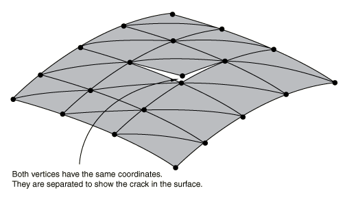
When defining three-dimensional surfaces formed by element faces, avoid
defining two surface nodes with the same coordinates. Such a definition can
give rise to a seam, or crack, in the surface as shown in
Figure 1.
Example of doubly defined surface node.
Using an Inadequate Surface Definition for the Desired Contact Conditions
Occasionally, surface definitions may not be suitable for modeling the
desired contact conditions in a problem.
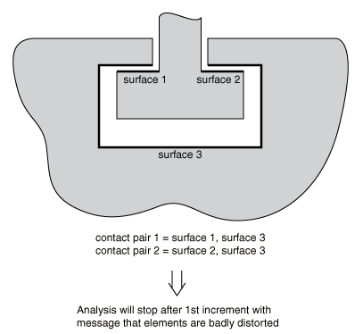
Figure 2
shows a two-dimensional model of a simple connection between two parts.
Surface definitions that are inadequate for the desired contact
conditions.
The surfaces shown in the figure are inadequate for the desired contact
conditions that are also shown. At the start of the simulation,
Abaqus/Explicit
will detect that some of the nodes on surface 3 are behind surfaces 1 and 2.
When the contact conditions are enforced, the motions of the surfaces will
likely cause badly distorted elements. One solution to this problem is shown in
Figure 3.
Surface definitions that are adequate for the desired contact
conditions.
The surfaces shown in that figure are suitable for the desired contact definition. Other
solutions, such as using a pure main-secondary contact pair, exist for this problem and may
be more suitable, depending on the details of the intended simulation.
Using Poorly Discretized Surfaces
Several problems are caused by surfaces created on very coarse meshes.
Penetrations with Coarsely Discretized Surfaces When Using Hard Surface Behavior
When a coarsely discretized surface is used as the secondary surface in a pure main-secondary
contact pair with hard surface behavior, an inaccurate solution may be produced as a
result of the gross penetration of the main surface into the secondary surface. This
situation is shown in Figure 4. This problem can be minimized if the contact pair can be switched to a balanced
main-secondary contact pair. However, some contact pairs in Abaqus/Explicit must always use a pure main-secondary formulation. In these cases the only solution to
gross penetration is to refine the secondary surface.
Main surface penetrations into the secondary surface due to coarse discretization.
Problems with Coarsely Discretized Rigid Surfaces
For rigid surfaces formed by element faces, inaccurate results may be obtained if too few
elements are used to represent a curved geometry. When a very coarse mesh is used on a
curved geometry, it is possible for secondary nodes to get “snagged” on the sharp
vertices.
In general, using a reasonable number of element faces to represent a curved
surface will not increase the computational time of the simulations. However, a
large number of element faces can significantly increase the memory that
Abaqus/Explicit
will need for the simulation. When a specific curved surface geometry can be
modeled, using an analytical rigid surface may provide a more accurate
geometric description while minimizing computational expense; see
Analytical Rigid Surface Definition.
Penalty Contact Behavior Sensitivity in Rigid-to-Rigid Interactions
The contact penalties are, in general, determined from stable time increment
considerations and masses of the nodes involved in contact. To compute a
reliable contact penalty when rigid bodies are contacting each other,
Abaqus/Explicit
accounts in a comprehensive fashion for the inertial properties of the rigid
bodies by distributing the mass of the rigid bodies at all nodes that might be
involved in contact. Hence, the final contact penalty will depend on the size
of the actual rigid surfaces that are included in the contact definitions.
Consequently, the contact response (forces, penetrations) will depend somewhat
on your choice in defining the contacting surfaces on the rigid bodies. If
large penetrations occur, specifying realistic inertial properties for the
rigid bodies will help in general to resolve the issue. Alternatively, you can
use a scaling factor for the penalties to enforce contact in a more accurate
fashion.
Conflicts with Boundary Conditions
If boundary constraints are applied to contact nodes on both surfaces of a
contact pair in the direction that the contact constraints are active, the
boundary constraints may override the contact constraints. For kinematic
contact, contact force related quantities will be output as the force necessary
to resolve the contact constraint in a single increment, causing misleading
results for these output quantities if the boundary constraints violate the
contact constraints. Contact force output for penalty contact does not show
this behavior since the contact force is proportional only to the current
penetration and does not depend on the time increment. Boundary constraints are
not affected by contact constraints.
Conflicts with Multi-Point Constraints
Using a multi-point constraint (MPC) with a
node on a surface that is part of an active kinematic contact pair can generate
conflicting kinematic constraints in the model.
Abaqus/Explicit
will not prevent you from using multi-point constraints on the nodes forming a
surface. If the contact constraints and the constraints formed by the
MPC are orthogonal, there will be no problems
with the simulations. If they are not orthogonal, the solution may be noisy as
Abaqus/Explicit
tries to satisfy the conflicting constraints. Since within each increment
kinematic contact constraints are applied after
MPCs are applied, the
MPCs on kinematic contact surfaces may be
slightly out of compliance.
In the case of an interaction between an
MPC and penalty contact, the
MPC is strictly enforced and any noncompliance
in the contact pair will be resisted by penalty forces.
Conflicting Contact Constraints on Shell Nodes with Hard Contact
When a shell or membrane is pinched between two main surfaces using two kinematic contact pairs
with hard contact behavior, one of the contact constraints will not be enforced exactly. In
a quasi-static analysis it may be observed that the pinched secondary node will oscillate
about an “equilibrium” penetration depth with a decay rate that depends on the time
increment and the ratio of the mass of the pinched node and the mass of the main surfaces.
Decreasing the time increment size will increase the decay rate (quasi-static equilibrium
will be reached more quickly). Reducing the mass of the nodes on the main surfaces (or
increasing the mass of the pinched nodes) will also increase the decay rate, although a high
ratio of secondary mass to main mass can also lead to numerical difficulties for kinematic
contact, as discussed below in Large Mass Mismatch between Contact Surfaces.
Applying the loads to the model gradually will reduce the amplitude of the oscillation. In
most analyses it is not desirable to alter the time increment or nodal masses arbitrarily,
so the decay rate of the oscillation will be fixed. Either the loading rate can be modified
or a softened contact model with contact damping can be used to control this oscillatory
behavior.
The quasi-static equilibrium penetration magnitude,
,
is approximately given by
where f is the normal contact force,
is the increment size, and m is the mass of the pinched
node. The quasi-static equilibrium penetration will be minimal if it is small
compared to the shell or membrane thickness. A change in the time increment
size or loading on the pinched surfaces during the analysis causes the
quasi-static equilibrium penetration to change, which can be responsible for
large accelerations of surface nodes and can contribute to solution noise
(typically, this behavior manifests as a jump in contact results such as
CPRESS). Similar noisy behavior for pinched
surfaces can occur across a step boundary, even if the time increment size is
uniform across the step boundary.
If one kinematic contact pair and one penalty contact pair are used to model
the same type of pinching problem, the kinematic constraint is enforced exactly
and the static value of the penetration in the penalty contact pair is somewhat
larger than that which occurs when kinematic contact is used for both contact
pairs (assuming that the penalty stiffness is set such that the analysis is
numerically stable for the time increment being used).
Multiple Kinematic Contact Constraints on Solid Nodes
If a node that is not attached to shell or membrane elements acts as a secondary node in two or
more simultaneous, kinematic contact constraints, the resulting contact corrections may be
erroneous, possibly causing the analysis to end with excessive element distortion. By “not
attached to shell or membrane elements” we are referring to nodes attached to solid elements
or point masses, for example. The majority of solid nodes typically are not involved in
simultaneous contacts, but there are common exceptions where three or more bodies meet at
corners. This limitation can be avoided by using penalty contact. For example, if a solid
surface acts as a secondary in two contact pairs and there is a possibility of simultaneous
contacts for individual secondary nodes, penalty enforcement of contact should be specified
for one or both of the contact pairs.
Redundant and Degenerate Contact Constraints
Redundant contact constraints are caused by overlapping or adjoining surfaces. For example, if
contact is specified between a single surface and multiple overlapping surfaces, the contact
constraints associated with the common nodes of the overlapping surfaces are redundant.
Degenerate contact constraints occur if the secondary surface and main surface of the same
contact pair contain common nodes (a contact constraint cannot be formed between a node and
itself).
If redundant kinematic contact constraints are specified, Abaqus/Explicit will consolidate the constraints if both contact pairs use pure main-secondary contact,
the secondary surfaces do not share facets, and the surface interaction and contact pair set
names are identical. If the contact pair definitions differ, the analysis will terminate
with an error, and one of the redundant constraints must be removed from the model
definition to continue the analysis.
Redundant penalty contact constraints may cause excessive initial
overclosure adjustments, creating gaps in the place of initial overclosures. To
correct this behavior, one of the constraints must be removed from the model
definition.
Redundant contact constraints involving both a penalty contact pair and a
kinematic contact pair cause inefficiencies in the analysis. The kinematic
contact constraints will override the penalty contact constraints, but the
penalty contact constraints will still be considered in the automatic time
increment estimate.
If the surfaces in a two-surface contact pair contain common nodes, the contact constraint for
each shared node cannot be generated. This is the equivalent of defining self-contact
between the shared nodes and each surface. However, the two-surface contact logic (unlike
the specialized self-contact logic) would erroneously detect contact between each shared
node and itself. When this condition occurs, Abaqus/Explicit redefines the secondary surfaces so that the shared nodes will not act as secondary nodes
in the contact pair. However, the shared nodes will still be used in the definition of a
main surface in the contact pair.
Large Mass Mismatch between Contact Surfaces
Often very little mass is assigned to rigid bodies in quasi-static
simulations because the mass has little influence on the physical problem.
However, specifying a small rigid body mass can adversely affect the kinematic
contact enforcement method. A force applied to a rigid body with very little
mass can cause a large predicted displacement of the rigid body within an
increment prior to the enforcement of contact constraints, so significant
penetration may be present in the “predicted” configuration for kinematic
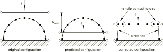
contact, as shown in
Figure 5.
Undesirable numerical behavior of contact algorithm resulting from
small rigid body mass.
With hard kinematic contact each secondary node that is penetrating its main surface in the
predicted configuration will be brought to the position of its tracked point on the main
surface in the corrected configuration, which, in this example, generates tensile contact
forces at the outer secondary nodes of the contact region. This undesirable effect can be
avoided by increasing the mass of the rigid body, which will reduce the predicted
displacement increment. A small rigid body mass can also adversely affect penalty
enforcement of contact because small penalty stiffnesses will be assigned.
Similar undesirable numerical behavior can occur for deformable-to-deformable contact if the
nodal masses of the main nodes are orders of magnitude less than those of the secondary
nodes. This problem can often be avoided in such cases by using the pure main-secondary
algorithm with the main surface containing the more massive nodes.
Contact Noise Associated with Limited Computer Precision for Hard Contact
Some contact noise may occur with hard contact models because of limited
computer precision. This noise is rarely significant in an analysis, but it may
be noticeable at the beginning of an analysis if initial displacements are used
to make the mesh comply with contact constraints. For example, if an adjustment
of
is made for an initial overclosure, a penetration of up to
may still exist in the first increment, where
is the “machine epsilon” of the computer. The machine epsilon of a given
computer is defined as the smallest positive number that can be added to 1 with
the computed result being greater than 1; on most systems
is approximately 6E−8 for single precision and 1E−16 for double precision. With
the kinematic contact algorithm you can attribute initial accelerations of up
to
to limited machine precision, where
is the time increment. For a single precision analysis in which
=1E−6
sec, initial accelerations of up to 6E4
sec−2
can be attributed to limited machine precision. These accelerations are
typically insignificant. They can be reduced by conducting the analysis with
double precision or by specifying the nodal coordinates to be more compliant
with contact constraints.
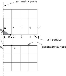
Finite-Sliding Contact near a Symmetry Plane
When a pure main-secondary contact constraint with finite sliding is defined near a symmetry
plane in the main surface, the corner secondary node (node A in Figure 6) can, under some circumstances, slide freely along the symmetry plane without
experiencing contact. If the main surface wraps around the corner (node 1), the secondary
node A may “track” on the main segment (1–6) on the symmetry plane,
rather than on main segment (1–2). The result may be an inaccurate representation of the
contact constraint as shown by the shaded area.
Contact near a symmetry plane. The main surface is wrapped around the corner.
If the main surface does not wrap around the corner (node 1 in Figure 7), the contact logic may give different results depending on how the symmetry boundary
conditions have been defined for the main node 1 on the symmetry plane. If the symmetry
boundary conditions on the main node are specified using boundary “type” format (i.e.,
XSYMM, YSYMM, or
ZSYMM—see Boundary Conditions), the main
surface is effectively extended beyond the symmetry plane (Figure 7); thus, the secondary node A will be detected as a “penetrated” node
(penetrated by distance a). Therefore, a correcting force would be
applied on secondary node A to push it below the main surface.
The main surface is extended across the symmetry plane because the symmetry boundary
condition at node 1 is specified using boundary type
XSYMM.
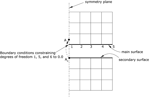
If the symmetry boundary conditions on the main node 1 are specified using “direct” format (i.e.,
specifying the components of translations and rotations that are fixed), the main surface is
not extended beyond the symmetry plane (Figure 8) and it is possible that contact will not be enforced correctly.
The main surface is not extended across the symmetry plane because the symmetry boundary
conditions at node 1 are specified using direct format.
To ensure proper enforcement of finite-sliding contact near symmetry planes, use balanced
main-secondary contact or use pure main-secondary contact without extending the surface onto
the symmetry plane and use symmetry “type” boundary conditions on the perimeter of the main
surface nodes as discussed above. Special consideration of small-sliding contact near a
symmetry plane is discussed in Contact Formulations for Contact Pairs in Abaqus/Explicit.
Specifying Initial Clearance Values Precisely
You can define initial clearances and contact directions precisely for the nodes on the secondary
surface (see Specifying Initial Clearance Values Precisely). The
initial clearance or overclosure value calculated at every secondary node based on the
coordinates of the secondary node and the main surface is overwritten by the value that you
specify; the coordinates of the secondary nodes are not altered. This technique permits
exact specification of initial clearances (and, possibly, contact directions) when they
would not be computed accurately enough from the nodal coordinates; for example, if the
initial clearance is very small compared to the coordinate values. It can be used only in
small-sliding contact analyses (Contact Formulations for Contact Pairs in Abaqus/Explicit).
When the balanced main-secondary contact algorithm is invoked for the contact pair, the initial
clearance values can be defined on one or both of the surfaces. Initial clearances defined
on contact surfaces that act only as main surfaces will be ignored.
Visualizing the Precise Initial Clearances for Small-Sliding Contact Pairs
Abaqus/Explicit does not adjust the coordinates of the secondary surface when precise initial clearances
are specified for small-sliding contact pairs (see Contact Initialization for Contact Pairs in Abaqus/Explicit). Therefore, the specified clearances cannot be
seen in a postprocessor. Thus, depending on the initial geometry of the surfaces and the magnitude of the
clearances or overclosures, the surfaces may appear open or closed in the postprocessor when
they are actually just in contact.