are often used in geotechnical applications, where pore pressure
continuity between material on opposite sides of an interface must be
maintained;
govern pore fluid flow across a contact interface and into a gap
region for nearby contact surfaces;
are applicable when pore pressure degrees of freedom are present on
both sides of a contact interface (if pore pressure degrees of freedom are
present on only one side of a contact interface, the surfaces are treated as
impermeable);
affect the pore fluid flow normal to the contact surfaces;
can apply to small- and finite-sliding contact formulations; and
assume that there is no fluid flowing tangentially to the surface.
Contact in coupled pore fluid diffusion/stress analysis involves
displacement constraints to resist penetrations and pore fluid contact
properties that influence the fluid flow. See
Coupled Pore Fluid Diffusion and Stress Analysis
for details on coupled pore fluid diffusion/stress analyses. See
Defining the Constitutive Response of Fluid within the Cohesive Element Gap
for details on the use of pore pressure cohesive elements as an alternative to
using contact models and pore fluid contact properties.
The pore fluid contact properties discussed in this section apply when pore
pressure degrees of freedom exist on both sides of a contact interface. In such
cases the calculated contact pressure is effective; it does not include the
pore fluid pressure contribution.
If only one side of a contact interface includes pore pressure degrees of
freedom, no fluid flow into or across the contact interface occurs. In this
case the reported contact pressure represents the total pressure, including the
effective structural and pore fluid pressure contributions; but only the
effective contact pressure is used for the computation of friction.
Including Pore Fluid Properties in a Contact Property Definition
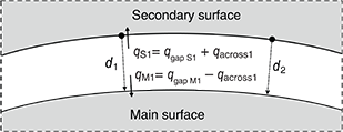
Abaqus/Standard assumes that pore fluid flows in the normal direction at a contact interface and does not
flow tangentially along the interface. Two contributions to the fluid flow into each surface
at a contact interface are generally present, as shown in Figure 1. The fluid flow into the main and secondary surface at corresponding points on the
interface are and , respectively.
One contribution () is associated with flow across the interface. A positive value of corresponds to flow out from the main surface and into the secondary
surface.
The other contribution ( for the secondary surface and for the main surface) is associated with removing or adding fluid from
the region between the surfaces while the gap distance is changing. The sign convention
is such that and are positive when these contributions flow into the respective
surfaces (while the gap width decreases). The sum of and (which is the same as the sum of and ) is equal to negative one times the rate of change of the gap width up
to the threshold distance discussed in Controlling the Distance within Which Pore Fluid Contact Properties Are Active.
In steady-state analyses the rate of separation of the surfaces is zero, so
the fluid flow contributions
and
are zero; all fluid flowing out of one surface flows into the other in
steady-state analyses.
Flow patterns in the interface contact element.
Pore fluid flow at a contact interface typically occurs even if contact
permeability characteristics are not explicitly specified in the contact
property definition. Alternatively, you can directly specify contact
permeability characteristics for enhanced control over the flow of fluid across
a contact interface and the type of constraint enforcement method.
Controlling the Distance within Which Pore Fluid Contact Properties Are Active
The models governing fluid flow across a contact interface are most
appropriate for two surfaces in contact or separated by a relatively small gap
distance. By default,
Abaqus
assumes no fluid flow occurs once the surfaces have separated by a distance
larger than the characteristic element length of the underlying surfaces.
Alternatively, you can directly specify a cutoff gap distance beyond which no
fluid flow occurs. Separate controls are provided for the contribution of fluid
flow across the interface ()
and the contribution of fluid flow into the interface
().
Controlling Contact Permeability Associated with Fluid Flow across a Contact Interface
where
and
are pore pressures at points on opposite sides of the interface. This
relationship implies that contact permeability across the interface is
infinite.
Alternatively, you can specify a contact permeability,
k, such that fluid flow across a contact interface
(,
discussed above in
Including Pore Fluid Properties in a Contact Property Definition)
is proportional to the difference in pore pressure magnitudes across the
interface:
When defining k directly, define it as
where
is the contact pressure transmitted across the interface between
A and B,
is the average of the pore pressures at A and
B,
is the average of the surface temperatures at A and
B, and
is the average of any predefined field variables at A
and B.
Figure 2
shows an example of k depending on the contact pressure.
Use tabular data to specify the value of k at one or more
contact pressures as p increases. The value of
k remains constant for contact pressures outside of the
interval defined by the data points. Once the surfaces have separated,
k remains at a constant value until the separation between
the surfaces exceeds the specified flow cutoff distance (see
Controlling the Distance within Which Pore Fluid Contact Properties Are Active),
at which point k drops to zero.
Contact-pressure-dependent contact permeability.
Defining Gap Permeability to Be a Function of Predefined Field Variables
In addition to the dependencies mentioned previously, the gap permeability
can be dependent on any number of predefined field variables,
.
To make the gap permeability depend on field variables, at least two data
points are required for each field variable value.
Controlling the Constraint Enforcement Method
The default enforcement method depends on whether the contact permeability
is specified. If contact permeability characteristics are not explicitly
specified, the continuity of pore pressure across the interface is approximated
with a penalty method (large permeability) for general contact and directly
enforced for contact pairs. You can optionally specify the penalty method for
contact pairs.
If contact permeability is specified, fluid flow consistent with the
specific permeability is directly enforced for both contact pairs and general
contact. If contact permeability is specified, the penalty method is not
applicable and not allowed.
Heat transfer can be considered simultaneously with pore fluid flow, in
which case heat flow across the contact interface can occur in conjunction with
fluid flow. These various contact property aspects are defined with separate
options as part of a single contact property definition that you assign to the
contact interaction; see
Thermal Contact Properties
for details on defining heat transfer properties.
Output
You can write the contact surface variables associated with the interaction
of contact pairs to the
Abaqus/Standard
data (.dat), results (.fil), and
output database (.odb) files. In addition to the surface
variables associated with the mechanical contact analysis (shear stresses,
contact pressures, etc.) several pore fluid-related variables (such as pore
fluid volume flux per unit area) on the contact interface can be reported. A
detailed discussion of these output requests can be found in
Surface Output from Abaqus/Standard
and
Writing Surface Output to the Output Database.
Abaqus/Standard
provides the following output variables related to the pore fluid interaction
of surfaces:
PFL
Pore volume flux per unit area leaving the secondary surface.
PFLA
PFL multiplied by the area associated with the
secondary node.
PTL
Time integrated PFL.
PTLA
Time integrated PFLA.
TPFL
Total pore volume flux leaving the secondary surface.