In
Abaqus/Explicit
integrated output can be requested either over a surface or over an element
set; in
Abaqus/Standard
integrated output can be requested over a surface.
An integrated output request is used to write the time history
of variables such as the total force transmitted across a surface, the total
mass of an element set, or the percentage change of the total mass of an
element set.
The integrated variables that can be written to the output database in
Abaqus/Explicit
are defined in
Integrated Variables.
The integrated variables that can be written to the output database in
Abaqus/Standard
are defined in
Section Variables.
Selecting the Surface over Which Integrated Output Is Required
You can specify the surface directly for an integrated output request.
Alternatively, you can associate an integrated output section that identifies
the surface (see
Integrated Output Section Definition)
with the integrated output request.
Integrated output can be requested for a surface that includes facets,
edges, or ends of various types of deformable elements. The surface can include
facets of three-dimensional solid elements and continuum shell elements; edges
of two-dimensional solid elements, membrane elements, conventional shell, and
surface elements; and ends of beam elements, pipe elements, and truss elements.
Specifying the Surface for Integrated Output Directly
If you specify the surface for an integrated output request directly, any
vector output variables are given with respect to a fixed global coordinate
system and the total moment transmitted across the surface, SOM, is computed about the fixed global origin. See
Element-Based Surface Definition
for information on defining element-based surfaces.
Specifying the Surface through an Integrated Output Section Definition
If you associate an integrated output section definition with an integrated output request, the
integrated output variables can be obtained in a local coordinate system that can
translate and rotate with the deformation (see Figure 1). In addition, the total moment transmitted across the surface,
SOM, can be computed about a moving
location.
User-defined local coordinate system.
Requesting Integrated Output for “Force-Flow” Studies
To study the “force-flow” through various paths in a model, you must create interior surfaces
that cut through one or more regions (similar to a cross-section) so that you can request
integrated output of the total force transmitted across these surfaces. You can create such
interior surfaces over the element facets, edges, or ends by cutting through one or more
regions of the model with a plane; see Creating Interior Cross-Section Surfaces for more
information.
Requesting Integrated Output over an Element Set in Abaqus/Explicit
You can request integrated output over an element set to output its total mass, the percentage
change of its total mass, its average rigid body motion, or any combination of these
variables. The element set must have been defined previously, and it can include any type of
elements. Only dedicated integrated output quantities are supported for Eulerian or discrete
particle element sets. These output quantities are defined in Integrated Variables.
Preselected output variables are available only when the integrated output
is requested over a surface. If integrated output is requested over an element
set, you must specify the variables on the data line.
If the integrated output is requested over a surface, you can request the
preselected integrated output variables SOF and SOM. In this case you can also specify additional variables as part
of the output request. Alternatively, you can request all integrated variables
applicable to the current procedure type. In this case any additional variables
that you specify are ignored. If you do not request the preselected variables
or all variables, you must specify the variables individually.
Limitations When Using Integrated Output Requests
Integrated output requests over a surface are subject to the following
limitations:
Integrated output can be requested over a surface that includes facets,
edges, or ends of various types of deformable elements. The surface can include
facets of three-dimensional solid elements and continuum shell elements; edges
of two-dimensional solid elements, membrane elements, conventional shell, and
surface elements; and ends of beam elements, pipe elements, and truss elements.
The surface should not contain facets of axisymmetric elements or facets of
rigid elements.
When defining the surface, elements on only one side of the surface must
be used.
Abaqus/Explicit
computes the integrated output variables using the stresses and hourglass-mode
forces in elements underlying the surface as in a free-body diagram.
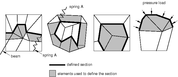
The defined surface must cut completely through the mesh, form a closed
surface, or be on the exterior of the body.
Figure 2
presents some typical cases of valid surfaces. If the surface cuts only
partially through the mesh, a valid free-body diagram cannot be isolated (see
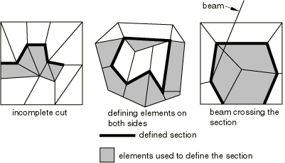
Figure 3)
and incorrect answers may be computed.
Elements attached to the surface can be on either side of the surface
but must not cross the defined surface.
Figure 3
presents a few invalid cases.
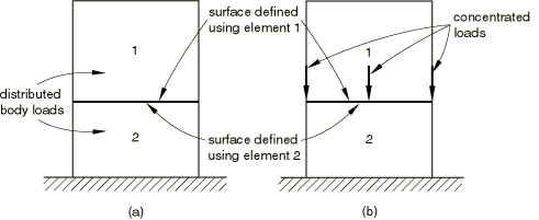
The total force and the total moment in the section are computed based
only on the stresses (internal forces) in the identified elements. Thus,
inaccurate results may be obtained if distributed body loads are present in
these elements since their effect on the total force in the section is not
included. Common examples are the inertial loading in dynamic analyses, gravity
loads, distributed body forces, and centrifugal loads. In these cases the total
force in the section may depend on the choice of elements used to define the
section as illustrated in
Figure 4(a).
Total force in the section.
Assuming that gravity loading is the only active load, the element
stresses will be different in the two elements. Hence, if the same surface is
defined first using element 1 and then using element 2, different answers for
the total force will be obtained. In a similar way the effects of any
distributed body fluxes (heat, electrical, etc.) prescribed in the identified
elements are not included.
Depending on which side of the surface is used to define the section,
different answers will be obtained in analyses similar to the case illustrated
in
Figure 4(b).
Assuming a quasi-static analysis with the concentrated loads shown in the
figure being the only active loads, a zero total force is reported if the
surface is defined using element 1 and a nonzero force equal to the sum of the
concentrated loads is obtained if the surface is defined using element 2.
If the nodes that are part of the integrated output surface also participate in
constraints (such as a tie constraint), the constraint force or flux is not included in
the integrated output.