Defining Pore Fluid Flow as a Function of the Current Pore Pressure in Consolidation Analysis
In consolidation analysis you can provide seepage coefficients and sink pore pressures on element faces or surfaces to control normal pore fluid flow from the interior of the region modeled to the exterior of the region.
The surface condition assumes that the pore fluid flows in proportion to the difference between the current pore pressure on the surface, , and some reference value of pore pressure, :
where
is the component of the pore fluid velocity in the direction of the outward normal to the surface;
is the seepage coefficient;
is the current pore pressure at this point on the surface; and
is a reference pore pressure value.
Specifying Element-Based Pore Fluid Flow
To define element-based pore fluid flow, specify the element or element set name; the distributed load type; the reference pore pressure, ; and the reference seepage coefficient, . The face of the elements upon which the normal flow is enforced is identified by a seepage distributed load type. The seepage types available depend on the element type (see About the Element Library).
Specifying Surface-Based Pore Fluid Flow
To define surface-based pore fluid flow, specify a surface name, the seepage flow type, the reference pore pressure, and the reference seepage coefficient. The element-based surface (see Element-Based Surface Definition) contains the element and face information.
Defining Drainage-Only Flow
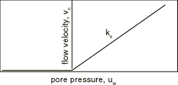
Drainage-only flow types can be specified for element-based or surface-based pore fluid flow to indicate that normal pore fluid flow occurs only from the interior to the exterior region of the model. The drainage-only flow surface condition assumes that the pore fluid flows in proportion to the magnitude of the current pore pressure on the surface, , when that pressure is positive:
where
is the component of the pore fluid velocity in the direction of the outward normal to the surface;
is the seepage coefficient; and
is the current pore pressure at this point on the surface.
Figure 1 illustrates this pore pressure–velocity relationship. This surface condition is designed for use with the total pore pressure formulation (see Coupled Pore Fluid Diffusion and Stress Analysis), mainly for cases where the phreatic surface intersects an exterior surface that is free to drain. See Calculation of phreatic surface in an earth dam for an example of this type of calculation.
When surface pore pressures are negative, the constraint will properly enforce the condition that no fluid can enter the interior region. When surface pore pressures are positive, the constraint will permit fluid flow from the interior to the exterior region of the model. When the seepage coefficient value, , is large, this flow will approximately enforce the requirement that the pore pressure should be zero on a freely draining surface. To achieve this condition, it is necessary to choose the value of to be much larger than a characteristic seepage coefficient for the material in the underlying elements:
where
- k
is the permeability of the underlying material;
is the fluid specific weight; and
- c
is a characteristic length of the underlying elements.
Values of will be adequate for most analyses. Larger values of could result in poor conditioning of the model. In all cases the freely draining flow type represents discontinuously nonlinear behavior, and its use may require appropriate solution controls (see Commonly Used Control Parameters).
Modifying or Removing Seepage Coefficients and Reference Pore Pressures
Seepage coefficients and reference pore pressures can be added, modified, or removed as described in About Loads.
Specifying a Time-Dependent Reference Pore Pressure
The magnitude of the reference pore pressure, , can be controlled by referring to an amplitude curve. If different variations are needed for different portions of the flow, repeat the flow definition with each referring to its own amplitude curve. See About Loads and Amplitude Curves for details.
Defining Nonuniform Flow in a User Subroutine
To define nonuniform flow, the variation of the reference pore pressure and the seepage coefficient as functions of position, time, pore pressure, etc. can be defined in user subroutine FLOW.