Crack propagation from a single crack tip – edge notch plate
Elements tested
CPE4
CPE8
Problem description
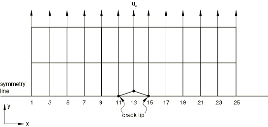
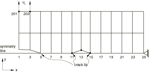
In the symmetry model the top half of a single-edge notch plate is modeled with a mesh of 2 × 6 CPE4 elements. The lower surface of the bottom row of elements defines the secondary surface of the partially bonded contact pair, and the main surface is defined by an analytical rigid surface. The main surface also lies along the symmetry plane. Nonzero displacement boundary conditions are applied at two nodes remote from the symmetry plane. The time for bond failure and the position of the node at which the bond failure occurs (obtained from pdebnods.inp) are used to give the crack length versus time data in pdebcrgr.inp. The crack opening displacement at a distance behind the crack tip (obtained from pdebnods.inp) is used to specify the data for the COD criterion in pdebcods.inp. The stresses at a distance ahead of the crack tip (obtained from pdebnods.inp) are used to specify the data in pdebnodsd.inp. The time from pdebnods.inp is also used to set the time period for each step in pdebchck.inp.
The complete mesh is analyzed in pdebnods2.inp, pdebcrgr2.inp, and pdebcods2.inp.
Input files pdebnodnlg.inp, pdebcrgnlg.inp, and pdebcodnlg.inp consider finite deformation and finite sliding. The crack length versus time data for pdebcrgnlg.inp and the COD data for pdebcodnlg.inp are obtained from pdebnodnlg.inp.
Results and discussion
The time at bond failure, the remaining fraction of the stress at debonding, the remaining debond stress, and all element stresses and strains must be the same for corresponding increments of tests pdebnods.inp, pdebcrgr.inp, and pdebcods.inp. At the total time corresponding to the end of each step in pdebchck.inp, the stresses and strains in the continuum elements are the same for all three tests. The same results are obtained for the models analyzed in pdebnods2.inp, pdebcrgr2.inp, and pdebcods2.inp.
The results obtained from pdebnodnlg.inp are compared with that of pdebcodnlg.inp and pdebcrgnlg.inp. The time at bond failure, the debond stress at failure, and the element stresses and strains are the same at the corresponding times.
Input files
- pdebnods.inp
-
Tests crack propagation using a critical stress criterion. The distance ahead of the crack tip at which the critical stress is evaluated is set to zero.
- pdebcrgr.inp
-
Tests crack propagation capability by using the crack length versus time criterion.
- pdebcods.inp
-
Tests crack propagation capability by using the COD criterion.
- pdebchck.inp
-
Checks this procedure without using any contact surface definitions by simulating the debonding by BOUNDARY, OP=NEW with multiple steps.
- pdebnodsd.inp
-
Tests crack propagation capability by considering the critical stress at a distance ahead of the crack tip. The distance ahead of the crack tip at which the critical stress is evaluated is varied from step to step.
- pdebnods2.inp
-
Tests crack propagation capability by using a critical stress criterion. The distance ahead of the crack tip at which the critical stress is evaluated is set to zero.
- pdebcrgr2.inp
-
Tests crack propagation capability by using the crack length versus time criterion.
- pdebcods2.inp
-
Tests crack propagation capability by using the COD criterion.
- pdebnodnlg.inp
-
Tests crack propagation capability by using a critical stress criterion. The distance ahead of the crack tip at which the critical stress is evaluated is set to zero.
- pdebcrgnlg.inp
-
Tests crack propagation capability by using the crack length versus time criterion.
- pdebcodnlg.inp
-
Tests crack propagation capability by using the COD criterion.
- pdebnods8.inp
-
Tests crack propagation capability by using a critical stress criterion. The distance ahead of the crack tip at which the critical stress is evaluated is set to zero.
- pdebcrgr8.inp
-
Tests crack propagation capability by using the crack length versus time criterion.
- pdebcods8.inp
-
Tests crack propagation capability by using the COD criterion.