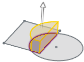
Extrude and Extrude Cut | ||
| ||
-
From the Features section of the action bar, click Extrude
 or Extrude Cut
 .
.
Tip: In the top menu of the dialog box, you can switch between Extrude  , Revolve
 , and Sweep
 features.
 -
Select the feature options in the
Extrude dialog box.
Note: The Add
 , Cut
, Cut
 , and New
 options are not selectable when creating your first
feature.
 Option Description 
Add. Creates a feature by adding multiple profiles. 
Cut. Creates a feature by subtracting one profile from another. 
New. Creates a feature from another feature. 
Solid. Creates a solid feature. 
Thin. Creates a feature with a constant wall thickness. To specify the wall thickness, drag the handle, or enter a value in the callout in the work area. You can specify the wall thickness to be equal in both directions from the profile's midplane by clicking Thin Midplane.

Surface. Creates a feature with a zero-thickness wall. -
Select the profiles to extrude.
 Direction 1 is available by default.
 -
Select the extrude type and end condition.
Not all end conditions are available in every situation.
- Blind. Extends the feature for the
specified distance.

- Midplane. Extends the feature for the specified distance from the
sketch plane in both directions.

- Through All Both. Extends the feature
from the sketch plane through all existing geometry in both directions.

- Through One Way. Extends the feature
from the sketch plane through all existing geometry in one direction.

- Up to Geometry. Extends the feature to the selected plane,
feature, or sketch entity.

- Up to Next. Extends the feature to the
next body.

- Up to Body. Extends the feature to the
selected body.

- Blind. Extends the feature for the
specified distance.
-
Set the extrude distance by dragging the handle or entering a
Distance value.

Note:The Dimension Edit Box is displayed as you sketch. Type the value for the dimension and press Enter.
- Optional:
To reverse the extrude direction, click
 or double-click the arrow handle to reverse the
direction.
- Optional:
To extrude a second direction, expand Direction 2 and
select an option from the menu.
- Off. Turns off Direction 2.
- Blind. Extends the feature for the specified distance.
- Up to Geometry. Extends the feature to the selected plane, feature, or sketch entity.
- Up to Next. Extends the feature to the next body.
- Up to Body. Extends the feature to the selected body.
- If Up to Geometry or Up to Body is selected, select an entity or body to which the extrude extends.
-
To taper the face of Direction 2, click
Draft and specify an angle. To reverse the
draft direction, click
 .
.
-
If Offset is available, you can extrude the
sketch profile an offset distance from the sketch plane's original
position. To reverse the direction, click
 .
.
-
To specify additional options, expand Advanced and
select one of the following Start Conditions from the
menu.
Applies an optional offset for the extrusion.
- At Sketch. Extrudes the sketch profile from the sketch plane.
- End to End. Extrudes the sketch profile the length of the entire sketch.
- From Offset. Extrudes the sketch profile an offset distance from the sketch plane's original position.
- From Selected Geometry. Extrudes the sketch profile an offset distance from the selected geometry.
- Optional:
To taper the face of the feature, click Draft and
specify an angle. To reverse the draft direction, click
 .
.
- Optional:
Select a merge option:
- Click Auto Merge to merge the extrude feature with all other possible bodies.
- If Auto Merge is not selected, select the bodies to merge with the extrude feature.
-
Click
 .
.