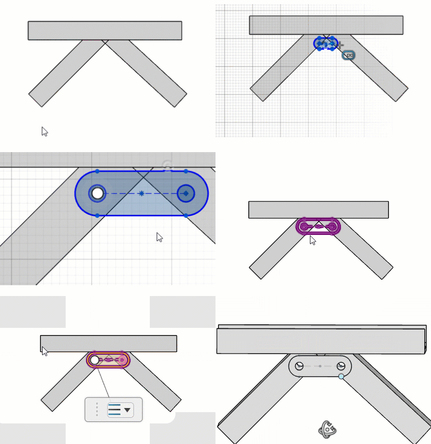
Creating Plates from Custom Profiles | |||
| |||
-
From the Structure section of the action bar,
click Plate
 .
.
-
In the dialog box, click Custom and from the Design Manager Tree
or work area, select a sketch.
The selected sketch appears in the Select Profile field.
- Specify a name for the custom profile.
- Optional:
Click parameters to be exposed to view the list of sketch
dimensions used in the custom profile.
You can edit the parameters at any time during plate creation.
- Optional:
Select Add cutouts to specify contours for cutouts.
The Cutout profiles option becomes available.
- Optional: From the work area, select closed sketch elements to use as contours for creating cutouts.
- Optional: Select Define Custom Origin to specify the location for the plate origin and from the work area, select a point to specify a plate origin.
-
Click Next to create a custom profile for the plate.
The preview of the plate with the associated axis system appears in the work area.
-
In the dialog box, under Thickness, from the
Thickness direction list, specify the direction for the plate.
See Thickness Direction Options.
Alternatively, from the work area, use the shortcut menu to adjust the direction of the thickness.
-
Specify a thickness value for the plate in the Overall thickness
field.
Alternatively, from the work area, use handles to adjust the thickness of the plate.
-
From the Design Manager tree or work area,
select members to cut with the specified cutout profile.
The selected members appear in the Target members field.
- Optional: Move the Preview cutouts slider to preview the cut on the target members.
-
Click
 .
The custom plate is created and stored in the library.