Display Relations Between Objects
In the diagram view, you can display the functional/logical connections of a selected object.
- In the diagram view, select a symbol
Important: You can select: - One object, to display all its relations with all objects in the diagram view.
- Several objects, to display the relations between the first selected object and every other selected object.

-
Click Display Relations
 from the Diagram section of the action bar.
Tip: The Display Relations command is also available in the context menu. The Display Relations dialog box appears and displays all the relations in the diagram view for this selected object.Note that the first column indicates if the functional/logical route exists for this relation in the diagram view.
- A gray cross: the corresponding route is created in the diagram view
- No cross: the corresponding route is not created in the diagram view
-
To create in the diagram view the route corresponding to a relation, select a row.
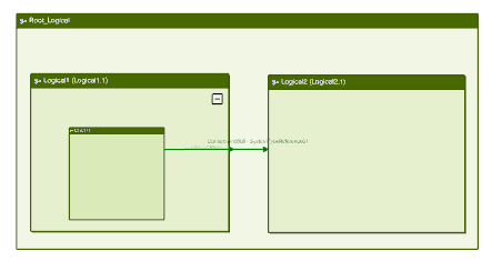
Tip: If needed, you can multiselect columns. A white cross appears in the first column. - Click OK.The following routes are created between:
- the parent and its child
- the child and the other object
Note: If a port representation is defined in the Data Setup Default Schematic Port Representation resource, it is placed in the diagram view.
